N64RGB - Installation question
I'm about to install the N64RGB (1.2) but I have a question.
What do I need to solder on the N64 output pins for sync-on-luma? I'm referring to this picture:
from the installation guide: installation guide
Do I just need to connect the GREEN, RED, BLUE, and both GND pins to the N64RGB board? (why are there two GND pins anyways if they are both connected to the same place?)
Also, is clean-sync really that much better than sync on luma when using a framemeister? (I already have N64 sync-on-luma cables so I would need to order new cables for csync)
Re: N64RGB - Installation question
If you have a cable that's been configured to sync on luma, you don't need to make any modifications to the multi-out side of the console. That's done for you in the cable.sofakng wrote: Also, is clean-sync really that much better than sync on luma when using a framemeister? (I already have N64 sync-on-luma cables so I would need to order new cables for csync)
Luma typically doesn't couple into your video like chroma does. It's when you get beyond the 3.5Mhz threshold (luma cut-off) that things can get nasty in a cable, so you'll be just fine.
Luma is a 75 ohm loaded signal, which Televisions & the Framemeister are designed for. C-Sync by design is a higher voltage TTL signal, it's not designed to directly work with 75 ohm source terminations.
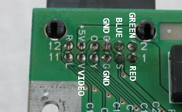
On that N64RGB board, you have both CS# (TTL) and CS75 (Television/Framemeister) C-Sync outputs available. But if you already have a sync-on-luma cable, it really isn't worth the trouble at that point.
Grab your sync-on-luma cable, install your RGB mod and call it a day.
Re: N64RGB - Installation question
There are two further things, which has to be considered:
First, I do have a late PAL N64 where the MultiAV pins for S-Video (7 and 8 ) are grounded. If this is the case in your console, too, you have to modify that to output e.g. CS75 on pin 7 (cutting ground connection, solder a wire from N64RGB to pin 7).
Second, if your N64 outputs S-Video, you may notice that the picture is shifted to the left (sync on stock luma vs. CS75). This is due to the fact that MaxII on the modding board has a lower processing delay compared to the N64 encoder. You have to answer it to yourself if you accept that or not. I'm totally with Voultar here: test first with in stock luma and then decide if a further modification is worth the work for you.
Re: N64RGB - Installation question
Thank you both so much for the help and information.
Just to confirm... I shouldn't need to solder anything to the multi-out PINs on the motherboard? (ie. I just need to solder the N64RGB to the VDC-NUS?)
It's confusing because the "Finishing Off" section of the installation guide says the following:
Just to confirm... I shouldn't need to solder anything to the multi-out PINs on the motherboard? (ie. I just need to solder the N64RGB to the VDC-NUS?)
It's confusing because the "Finishing Off" section of the installation guide says the following:
A standard installation has four wires soldered between the N64RGB board output pads and the Nintendo A/V output socket. Red, Green, Blue, Ground. Use the extra wires from the colourful ribbon cable.
Re: N64RGB - Installation question
You have to solder at least the three video channels (red, green and blue, taken from the N64RGB output section), otherwise how do you pretend to see something?
Re: N64RGB - Installation question
OK - Sorry, I didn't know it the output was backed through the VDC-NUS or something.
So do I need to solder the RGB and both GND pins then?
I was also unsure if I needed to disconnect any existing signals to those RGB pins. If I solder the N64RGB to them, then isn't both the native RGB of the N64 being sent to those pins AND the N64RGB RGB output?
So do I need to solder the RGB and both GND pins then?
I was also unsure if I needed to disconnect any existing signals to those RGB pins. If I solder the N64RGB to them, then isn't both the native RGB of the N64 being sent to those pins AND the N64RGB RGB output?
Re: N64RGB - Installation question
You can solder one GND point, two are redundant IMHO.sofakng wrote:OK - Sorry, I didn't know it the output was backed through the VDC-NUS or something.
So do I need to solder the RGB and both GND pins then?
I was also unsure if I needed to disconnect any existing signals to those RGB pins. If I solder the N64RGB to them, then isn't both the native RGB of the N64 being sent to those pins AND the N64RGB RGB output?
There are no native RGB signals wired to the MultiAV, as far as I know.
Re: N64RGB - Installation question
I always solder both ground pads / ends to have a good ground connection
Re: N64RGB - Installation question
OK - Thanks everybody!
Today I'm going to install the borti de-blur firmware on my new N64RGB board and also install the new borti SNES RGB bypass in my SNES 1CHIP-03.
Thanks again so much!
Today I'm going to install the borti de-blur firmware on my new N64RGB board and also install the new borti SNES RGB bypass in my SNES 1CHIP-03.
Thanks again so much!
Re: N64RGB - Installation question
borti4938's PCBs are amazing!sofakng wrote:OK - Thanks everybody!
Today I'm going to install the borti de-blur firmware on my new N64RGB board and also install the new borti SNES RGB bypass in my SNES 1CHIP-03.
Thanks again so much!
Good work!
Re: N64RGB - Installation question
Yeah, the boards are amazing but I am not!
I just finished my installation... and I put the expansion pack in backwards. Now the red light won't turn on so I think I might of fried the console?
However, I'm reading reports that I just need to let it sit and let the breakers reset? Are there any fuses that I can check?
I just finished my installation... and I put the expansion pack in backwards. Now the red light won't turn on so I think I might of fried the console?
However, I'm reading reports that I just need to let it sit and let the breakers reset? Are there any fuses that I can check?
Re: N64RGB - Installation question
Could you post some pics of your work? It would help us.
Re: N64RGB - Installation question
The N64 PSU has a self-resetting fuse, so just let it sit for a while and try again.
Re: N64RGB - Installation question
Thanks so much!
I tried about an hour afterwards and it still didn't work but I just tried it again and it booted my EverDrive successfully. Phew! Hopefully no permanent damage.
The N64RGB seems to be working perfectly at first glance.
Thanks again everybody for the help!
I tried about an hour afterwards and it still didn't work but I just tried it again and it booted my EverDrive successfully. Phew! Hopefully no permanent damage.
The N64RGB seems to be working perfectly at first glance.
Thanks again everybody for the help!
Re: N64RGB - Installation question
OK - So I thought everything was good but I'm getting RGB jailbars (is that the correct term?) down the entire image:
I don't think I saw them until I put the system completely back together and screwed everything down. I could definitely be mistaken though since I only tested it for a second to verify it booted, etc. I also made sure to keep the digital ribbon cable as far as possible from the analog ribbon cable.
Also, I only wired the RGB and GND pins on the multi-out connector as instructed above. My cable is using sync-on-luma (from retrogamingcables.co.uk).
The good news is that I was able to flash borti's firmware and all the IGR buttons work correctly and I can see the deblur working
-
mikejmoffitt
- Posts: 629
- Joined: Fri Jan 08, 2016 7:26 am
- Location: Tokyo, Japan
Re: N64RGB - Installation question
That's not chroma coupling, that looks like interference from the RCP video data.
See if the jailbars change a little as objects move around the screen. The Super Smash Bros character-select hands are a good way to test this.
Re: N64RGB - Installation question
You may not have the ribbon cable soldered securely. When I modded my brother's N64, I didn't solder the ribbon cable quite right and so the image looked kind of strange. What I found helps is if you use a bit of flux and take it easy on the soldering iron so you don't damage the ribbon cable (or RCP traces).
Re: N64RGB - Installation question
I've just taken a bunch of images on my DSLR.
Would anybody mind taking a look and see if you spot any problems?
http://imgur.com/a/xF99g
I'm really trying to improve my soldering but I know it's still not great. I'm using a Hakko FX-888D with lots of flux but so many of those soldering points are quite small or close to other points
Would anybody mind taking a look and see if you spot any problems?
http://imgur.com/a/xF99g
I'm really trying to improve my soldering but I know it's still not great. I'm using a Hakko FX-888D with lots of flux but so many of those soldering points are quite small or close to other points
-
mikejmoffitt
- Posts: 629
- Joined: Fri Jan 08, 2016 7:26 am
- Location: Tokyo, Japan
Re: N64RGB - Installation question
I don't think your wiring is the issue. A wiring mistake wouldn't transform a solid-colored area into a pattern like that. That looks like power rail interference.
Re: N64RGB - Installation question
Any idea what I can do to fix it?
Re: N64RGB - Installation question
Is it likely that I permanently damaged something when I inserted the expansion pack backwards? I just want to make sure this is something that can be fixed before I desolder the N64RGB and buy another used N64... :/
Re: N64RGB - Installation question
Do you use a Framemeister or another Scaler? Do you have test it plugging the console directly into your TV?
I've seen a similar picture before somewhere here but cannot find it at the moment...
Re: N64RGB - Installation question
I'm using a Framemeister and I have no other RGB devices. However, my other SCART/RGB consoles are working fine.
I also just spent the past few hours rewiring everything a couple of times to get it as perfect as possible and it seems to have improved but I still have lots of bars. (I'll take a picture later)
However, this time I can move around the ribbon cables and the interference changes so I'm going to try rewiring the multi-out connector and routing the wires all-the-way around the other side to move as far as possible from the data ribbon. After that I'm out of ideas
I don't have any "shielded" cable, but I could just use thicker gauge wire, right?
EDIT: Here are the latest pictures after I resoldered everything: http://imgur.com/a/fN6bs
Re: N64RGB - Installation question
sofakng,
This problem is usually caused by placing the analog video wires too close to the digital video wires. Though the effect is not normally as bad as in the first photos.
Perhaps there is excessive noise on the 3.3V power rail... Do you have a electrolytic capacitor of 100u to 220u lying around that you could solder between the 3V3 and GND pads on the N64RGB board?
Re: N64RGB - Installation question
Will Tim's v1.2 N64RGB board output pure sync from any Nintendo 64 revision after installation, or only from the CPU-03 and older motherboards which still have pure sync wired in?
-
bobrocks95
- Posts: 3471
- Joined: Mon Apr 30, 2012 2:27 am
- Location: Kentucky
Re: N64RGB - Installation question
It generates its own in the CPLD I believe. So all motherboards.GeneraLight wrote:Will Tim's v1.2 N64RGB board output pure sync from any Nintendo 64 revision after installation, or only from the CPU-03 and older motherboards which still have pure sync wired in?
PS1 Disc-Based Game ID BIOS patch for MemCard Pro and SD2PSX automatic VMC switching.
Re: N64RGB - Installation question
Alright.bobrocks95 wrote:It generates its own in the CPLD I believe. So all motherboards.GeneraLight wrote:Will Tim's v1.2 N64RGB board output pure sync from any Nintendo 64 revision after installation, or only from the CPU-03 and older motherboards which still have pure sync wired in?
Is there any documentation of framerate differences between N64 motherboard revisions? Do newer models have less drops and more stable fps than older models, or vice-versa?
I heard CPU-08s are the most ideal for overclocking mods. But from what I've seen, overclocking mods just speed the game up and don't give more frames-per-second at the same speed.
Re: N64RGB - Installation question
Tim, thanks so much for the help (and developing the board in the first place!).viletim wrote:sofakng,
This problem is usually caused by placing the analog video wires too close to the digital video wires. Though the effect is not normally as bad as in the first photos.
Perhaps there is excessive noise on the 3.3V power rail... Do you have a electrolytic capacitor of 100u to 220u lying around that you could solder between the 3V3 and GND pads on the N64RGB board?
I think I've narrowed down the problem to the bend I made in the ribbon cable. I can't see any physical damage, but when I squeeze on the bend the interference gets much worse and when I straighten the cable, it becomes much better.
To replace the ribbon cable, I'm using 30 gauge silicon wire (fine-strand) which seems similar to the ribbon cable but each wire is separate/flexible. I'm almost finished but have a few more wires to go which I'll do tomorrow.
I can stop at my local radio shack tomorrow and pickup a capacitor. Is 220uf better than 100uf for filtering the noise? (normally I'd order from digikey/mouser but not for just one capacitor...) I'm guessing you are referring to something like this?
Thanks again so much!
Re: N64RGB - Installation question
I think the problem is you have a bad connection on one of the low order data line D0, D1, D2. The bad connection is either at the DAC or a break early on in the wire. This data line is floating and the transitions from the other data lines are coupled into it from the close proximity. That's why when you fold the ribbon cable over itself it gets worse.
Use your multimeter to check the continuity of each wire in the digital video ribbon cable.
Re: N64RGB - Installation question
Thanks again Tim. I'll check the continuity because I'm curious, but I've already rewired it using the silicon wire I mentioned above. Do you see any problems with using that?