TV RGB mod thread
Re: TV RGB mod thread
Trying to RGB mod my 32" Panasonic TV, model CT-32G13W. I removed the OSD lines and tapped in my RGB and pulled blank high to 5v. I hooked up my Neo Geo MVS and used the composite in for sync. Here is what I got right off.
Just need to figure out how to get those bars out of it. This is the only thing I have to test with at the moment. I don't have any other consoles with RGB at the moment, more to come of course! So what is left to do to get this working good?
-
buttersoft
- Posts: 383
- Joined: Sun Jul 24, 2016 7:49 am
Re: TV RGB mod thread
Nice to know I'm in good company. As i said, the schematics for Asia (and presumably for Australia) show a separate Micom chip, and that separate chip feeds the neckboard directly. I don't see why you'd bother, if you didn't have a cheaper Jungle IC that didn't take RGB-in. The Euro version, or some instances of it, had SCART - and I note that cheaper versions of the chassis used exactly the same components, but had a SCARTkill resistor to jump the ability to switch SCART on, in some way. My board seems to have that resistor, but removing it made no change.
I'm guessing the problem i have with delivering amped RGB direct to the neckboard lies in delivering too much current, and there's some sort of feedback loop reacting to that. Or possibly that the RGB im' producing isn't amped right, and the black level is resetting, again via some sort of loop. But those are just guesses - Tim will no doubt come in and tell me I'm wrong again I think if I build a two stage amp, using back-to-back 7314's, i can get a stable picture,but i want to confirm that. And doing so produces a ton of noise. Earlier in this thread I did read about turning down the contrast, colour and brightness to nothing. I'll give that a try, and try to measure the RGB coming out of the Micom directly as well.
mikejmoffitt wrote:Buttersoft, your experience resembles my first attempt on a 20" trinitron TV - fading from too bright, briefly "just right", then going darker. I did not ever properly solve it, so if you figure it out, I'd be interested in what you did.
-
KnuckleheadFlow
- Posts: 111
- Joined: Tue Jul 26, 2016 1:40 pm
Re: TV RGB mod thread
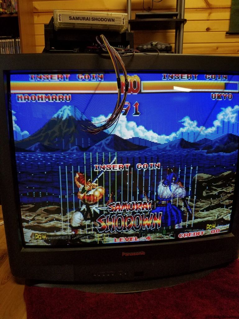
Seeing as how some of the bars go behind the characters while some go in front makes me think the problem is with the MVS and not the TV. Do you have an arcade monitor to connect it to?Devalis wrote:Trying to RGB mod my 32" Panasonic TV, model CT-32G13W. I removed the OSD lines and tapped in my RGB and pulled blank high to 5v. I hooked up my Neo Geo MVS and used the composite in for sync. Here is what I got right off.
Just need to figure out how to get those bars out of it. This is the only thing I have to test with at the moment. I don't have any other consoles with RGB at the moment, more to come of course! So what is left to do to get this working good?
From what I can tell, the picture looks dope, other than the bars. Any mods to the MVS? I'd have thought the voltages would be too high for a TV, more in the 2-3 Vpp range. Got a spec sheet for that Panasonic's jungle IC? Curious as to what voltage those RGB pins expect.
Re: TV RGB mod thread
Well......it is with great sadness that I inform you I've modded my 32" sony CRT TV into one that doesn't work. I just don't have the skills required to work on things that have small surface mounted components. Time to admit defeat and just get another TV that has component YPbPr input and use a SCART converter instead.
Dang....
Dang....
Re: TV RGB mod thread
I figured out the lines were caused by a bad connection. I reseated the cart and the picture came in bright and clean. The only thing that worries me a little is when the screen goes white, the lettering at the top and bottom will move off screen. I don't know if it's supposed to do that or what. Also, I need to know if I need to put any input protection on my new RGB input...
also, here is the datasheet on the jungle IC
http://pdf1.alldatasheet.com/datasheet- ... 5165K.html
also, here is the datasheet on the jungle IC
http://pdf1.alldatasheet.com/datasheet- ... 5165K.html
Re: TV RGB mod thread
Have you ever connected an MVS (or any other arcade board) to an RGB-modded TV chassis? Consoles are one thing, but impedance mismatch is giving me fits. I've been banging my head against such a project for a couple months, but can't get it quite right.mikejmoffitt wrote:I picked up another 25" TV today intending to do a tube swap on a Neo-Geo machine. If the tube swap doesn't work out, it's still a good tube and TV, so I'll see about RGB modding it. At a glance the OSD looks RGB-driven, so I bet it will not be difficult.
-
KnuckleheadFlow
- Posts: 111
- Joined: Tue Jul 26, 2016 1:40 pm
Re: TV RGB mod thread
How are you reducing the MVS's RGB signal (< 3 Vpp) to the TV's level (< 1 Vpp)? Earlier I posted a link to a DIY supergun with SCART RGB output. Take a look at that.
-
mikejmoffitt
- Posts: 629
- Joined: Fri Jan 08, 2016 7:26 am
- Location: Tokyo, Japan
Re: TV RGB mod thread
I've connected a bunch of MVS systems to my RGB modded TVs and nothing was out of the ordinary. I terminate my outputs with a 75 ohm resistor in series on the output, to match the termination of the TV.berq wrote:Have you ever connected an MVS (or any other arcade board) to an RGB-modded TV chassis? Consoles are one thing, but impedance mismatch is giving me fits. I've been banging my head against such a project for a couple months, but can't get it quite right.mikejmoffitt wrote:I picked up another 25" TV today intending to do a tube swap on a Neo-Geo machine. If the tube swap doesn't work out, it's still a good tube and TV, so I'll see about RGB modding it. At a glance the OSD looks RGB-driven, so I bet it will not be difficult.
Re: TV RGB mod thread
The only other thing I've hooked it up to is a Sony PVM, and it looked great on there.
-
buttersoft
- Posts: 383
- Joined: Sun Jul 24, 2016 7:49 am
Re: TV RGB mod thread
If you mean the whole image gets larger when it gets brighter... It's called bloom, and no, it's not really meant to happen. It always does though, even on the best sets a tiny bit, getting slowly worse as time goes on. I think it's the caps aging, though it by no means indicates they're about to fail.Devalis wrote:when the screen goes white, the lettering at the top and bottom will move off screen. I don't know if it's supposed to do that or what.
Re: TV RGB mod thread
I was thinking about recapping the set anyway. So you think putting the 75 ohm resistors on the output on the MVS will bring the voltages into range? If so, should I also put one on the sync?
Re: TV RGB mod thread
That was a good read. Thanks. Unfortunately, even with the MVS signal divided down to the right voltage, the image is still too dark.KnuckleheadFlow wrote:How are you reducing the MVS's RGB signal (< 3 Vpp) to the TV's level (< 1 Vpp)? Earlier I posted a link to a DIY supergun with SCART RGB output. Take a look at that.
I'd get into more detail, but this thread is getting kinda schizophrenic with all the different projects converging on it. Which is cool. I like that so many people are pumping new life into CRTs. But I'd already started chronicling my progress over on the neo-geo.com boards. If you're ever over that way, I'd be honored if you'd stop by.
-
mikejmoffitt
- Posts: 629
- Joined: Fri Jan 08, 2016 7:26 am
- Location: Tokyo, Japan
Re: TV RGB mod thread
If you are losing dark details, and/or you are having streaking issues depending on the game / content, you might be having a clamping problem.
Re: TV RGB mod thread
I think some monitors are worse than others regarding blooming. I fully recapped an old arcade monitor recently (some 30+ caps) and now the picture is nice and the colors are great, however, it blooms just like it did before.buttersoft wrote:If you mean the whole image gets larger when it gets brighter... It's called bloom, and no, it's not really meant to happen. It always does though, even on the best sets a tiny bit, getting slowly worse as time goes on. I think it's the caps aging, though it by no means indicates they're about to fail.
Turning down the brightness helps somewhat.
-
KnuckleheadFlow
- Posts: 111
- Joined: Tue Jul 26, 2016 1:40 pm
Re: TV RGB mod thread
A little off topic but I hope this doesn't discourage you (or anyone else) from further modding. Don't throw that TV out yet, though. You may get there soon enough. First surface mount mods I did looked like balls. Literally; solder balls all over the place. So bad even Drakkon would've sneered at it. Surface mount stuff can be tricky, but a little practice gets acceptable results. The caveat being you need 5 other things:Shoryukev wrote:Well......it is with great sadness that I inform you I've modded my 32" sony CRT TV into one that doesn't work. I just don't have the skills required to work on things that have small surface mounted components. Time to admit defeat and just get another TV that has component YPbPr input and use a SCART converter instead.
Dang....
1) a temp controlled soldering iron. There are good-enough Hakko knockoffs like the $24 YiHUA 936
2) small (0.8-1.2mm) wedge/screwdriver tips. Forget those bullshit cones.
3) fine and ultra fine solder. Having 0.015" diameter really helps with small stuff
4) magnification. Not to inspect, but to use while you work. I use a stereo microscope, but one of those big magnifying lenses on a flexible arm, or those glasses with the jeweller's loupe things should do. My vision is like the one thing that hasn't started going to shit, I really didn't think I needed magnification but I always wanted a microscope and got a good deal on eBay. I quickly realized having one that everything blownup like that made my movements significantly finer somehow. And I'm rather clumsy working with my hands.
5) *copious* amounts of flux paste. Smear that shit. Plain rosin flux is cheap, works good though it can be a little annoying to clean
With those, it really just takes a handfull of times practicing on junk PCBs to get you there. That said, though I can lay down a hundred picture perfect joints on surface mount ICs, caps and resistors still give me headaches and often end up slightly askew. So it goes.
Dave Jones of the EEVBlog on youtube has some good, detailed videos for this. Some people can't stand his voice but it never bothered me lol.
Hmm, shame about that. I'm thinking about making a CMVS myself, leaning towards using an 1C.berq wrote:That was a good read. Thanks. Unfortunately, even with the MVS signal divided down to the right voltage, the image is still too dark.
I'd get into more detail, but this thread is getting kinda schizophrenic with all the different projects converging on it. Which is cool. I like that so many people are pumping new life into CRTs. But I'd already started chronicling my progress over on the neo-geo.com boards. If you're ever over that way, I'd be honored if you'd stop by.
Re: TV RGB mod thread
It hasn't discouraged me, but I know my boundaries. I am just terrible with dealing with really small parts right now lol, I'm sure at some point I'll get better at it. Kinda sucks I butchered the TV, but I got it off craigslist for free a few years ago anyways so I'm not sweating it. I really need to get a magnifying glass and an articulating table clamp to hold things while I work on them. I've modded several of my consoles and enjoy the projects.KnuckleheadFlow wrote:A little off topic but I hope this doesn't discourage you (or anyone else) from further modding. Don't throw that TV out yet, though. You may get there soon enough. First surface mount mods I did looked like balls. Literally; solder balls all over the place. So bad even Drakkon would've sneered at it. Surface mount stuff can be tricky, but a little practice gets acceptable results. The caveat being you need 5 other things:Shoryukev wrote:Well......it is with great sadness that I inform you I've modded my 32" sony CRT TV into one that doesn't work. I just don't have the skills required to work on things that have small surface mounted components. Time to admit defeat and just get another TV that has component YPbPr input and use a SCART converter instead.
Dang....
1) a temp controlled soldering iron. There are good-enough Hakko knockoffs like the $24 YiHUA 936
2) small (0.8-1.2mm) wedge/screwdriver tips. Forget those bullshit cones.
3) fine and ultra fine solder. Having 0.015" diameter really helps with small stuff
4) magnification. Not to inspect, but to use while you work. I use a stereo microscope, but one of those big magnifying lenses on a flexible arm, or those glasses with the jeweller's loupe things should do. My vision is like the one thing that hasn't started going to shit, I really didn't think I needed magnification but I always wanted a microscope and got a good deal on eBay. I quickly realized having one that everything blownup like that made my movements significantly finer somehow. And I'm rather clumsy working with my hands.
5) *copious* amounts of flux paste. Smear that shit. Plain rosin flux is cheap, works good though it can be a little annoying to clean
With those, it really just takes a handfull of times practicing on junk PCBs to get you there. That said, though I can lay down a hundred picture perfect joints on surface mount ICs, caps and resistors still give me headaches and often end up slightly askew. So it goes.
Dave Jones of the EEVBlog on youtube has some good, detailed videos for this. Some people can't stand his voice but it never bothered me lol.
If nothing else at least I already found a replacement, found a 32" JVC CRT with a high line count on craigslist for $20 to use until I get good enough to try again. It was dealing with the surface mount capacitors on the board of my Sony that did me in lol
Re: TV RGB mod thread
Don't attempt to drive the neck board with the signal directly from an AV device. It's not going to work.buttersoft wrote: I'm guessing the problem i have with delivering amped RGB direct to the neckboard lies in delivering too much current, and there's some sort of feedback loop reacting to that. Or possibly that the RGB im' producing isn't amped right, and the black level is resetting, again via some sort of loop. But those are just guesses - Tim will no doubt come in and tell me I'm wrong again ;) I think if I build a two stage amp, using back-to-back 7314's, i can get a stable picture,but i want to confirm that. And doing so produces a ton of noise. Earlier in this thread I did read about turning down the contrast, colour and brightness to nothing. I'll give that a try, and try to measure the RGB coming out of the Micom directly as well.
If you want to replace the RGB preamplifier (ie the jungle IC) with your own it must have the following features:
1) Clamp the AC coupled video to a DC level so black is always at a constant voltage.
2) Provide variable gain and bias adjustments that are different for each channel. They need to be adjusted so they match the characteristics of the picture tube (this is done by the jungle IC normally, with settings stored in the micro's EEPROM).
3) The gain must be electronically variable by the ABL (Auto Beam Limiting) voltage. This basically a measurement of the anode current into the picture tube. If it is too high the contrast should be decreased, which causes the anode current to go down. It's an essential feedback loop. Without it a bright scene may cause the high voltage supply to drop out of regulation and as that's directly connected to the horizontal output stage it causes geometric distortion too.
4) The video needs to be blanked during retrace. The allows the user to turn up the brightness without seeing retrace lines. The blanking signal timing is normally generated from the signals fed back from horizontal and vertical output sections.
The micro's OSD out is muxed with the output of the jungle IC because some versions of the chassis require the RGB input for SCART. If one version has to be this way, might as well make them all like that. The TV design engineers don't want to work too hard. The OSD is digital and is generated by the TV itself. Because it's digital there's no need to bother with clamping and blanking. It restricts the generated video to what it can safely do without beam current feedback.buttersoft wrote:Nice to know I'm in good company. As i said, the schematics for Asia (and presumably for Australia) show a separate Micom chip, and that separate chip feeds the neckboard directly. I don't see why you'd bother, if you didn't have a cheaper Jungle IC that didn't take RGB-in. The Euro version, or some instances of it, had SCART - and I note that cheaper versions of the chassis used exactly the same components, but had a SCARTkill resistor to jump the ability to switch SCART on, in some way. My board seems to have that resistor, but removing it made no change.
-
buttersoft
- Posts: 383
- Joined: Sun Jul 24, 2016 7:49 am
Re: TV RGB mod thread
Sometimes you’re so far ahead of me I have trouble following. The last 6-7 pages of the schematic are the connection diagrams. The Euro version’s TTX micro feeds the TDA8842’s RGB inputs (though not the blanking pin?) My version has the Non-TTX micro, which feeds the neckboard. And it has a TDA8841, without SECAM capability, not the 8842 shown. Is that what you were saying...? Aren't there two versions, that work slightly differently?viletim wrote:The micro's OSD out is muxed with the output of the jungle IC because some versions of the chassis require the RGB input for SCART. If one version has to be this way, might as well make them all like that.
Schematic - https://my.mixtape.moe/zwwyvm.pdf
Jungle IC - https://my.mixtape.moe/hiflqk.pdf
The datasheet for the TDA8841 indicates RGB inputs, I just can’t get them to work. If they’ve been disabled internally, or by the micro, would replacing the chip, maybe with a higher-end 884X, work? If not, or if I can’t find one, is there a chip you’d suggest?
Thanks for the reply, the help you provide is amazing. If you’re willing to post, I’m willing to listen.
EDIT: I do wonder if there's a mistake in the schematic, in that the EU version's TTX micro does feed the blanking pin. The TTX-Bus connection on the micro shows a wire for it.
Re: TV RGB mod thread
anyone get a chance to look at the datasheet I posted, see if it can handle the output of the MVS?
-
KnuckleheadFlow
- Posts: 111
- Joined: Tue Jul 26, 2016 1:40 pm
Re: TV RGB mod thread
You sure that's the right chip? Pins 4, 5 and 6 on that datasheet show 0-5 V square pulse input; in other words, digital RGB.Devalis wrote:anyone get a chance to look at the datasheet I posted, see if it can handle the output of the MVS?
Re: TV RGB mod thread
Low cost TV chassis are often desiged to accomodate lots of variants. In you case I there's a version with and without teletext. With and without SCART. It appears one combination requires SCART and OSD at the same time, hence the OSD connected past the jungle IC. This jungle IC is designed for operation like this it seems. There's a note about it on page 15 of the datasheet.buttersoft wrote:Sometimes you’re so far ahead of me I have trouble following. The last 6-7 pages of the schematic are the connection diagrams. The Euro version’s TTX micro feeds the TDA8842’s RGB inputs (though not the blanking pin?) My version has the Non-TTX micro, which feeds the neckboard. And it has a TDA8841, without SECAM capability, not the 8842 shown. Is that what you were saying...? Aren't there two versions, that work slightly differently?viletim wrote:The micro's OSD out is muxed with the output of the jungle IC because some versions of the chassis require the RGB input for SCART. If one version has to be this way, might as well make them all like that.
It's a good idea to verify that the manual and chassis match. Service manuals are notorious for errors and ommisions.buttersoft wrote: Schematic - https://my.mixtape.moe/zwwyvm.pdf
Jungle IC - https://my.mixtape.moe/hiflqk.pdf
The datasheet for the TDA8841 indicates RGB inputs, I just can’t get them to work. If they’ve been disabled internally, or by the micro, would replacing the chip, maybe with a higher-end 884X, work? If not, or if I can’t find one, is there a chip you’d suggest?
Thanks for the reply, the help you provide is amazing. If you’re willing to post, I’m willing to listen.
EDIT: I do wonder if there's a mistake in the schematic, in that the EU version's TTX micro does feed the blanking pin. The TTX-Bus connection on the micro shows a wire for it.
Anyway, let's work out how to get RGB into TDA8841. It's got one of those paper-saving datasheets, 10 different parts for extra confusion. The TDA8841 is a 56 pin DIP isn't it? Page 5 for pinout. R, G, B, into pins 23, 24, 25. 'Fast blanking' (RGB enable) into pin 26 (0.9 to 3.0 V). Page 15 of the datasheet mentions that fast blanking for RGB-1 is controlled by the IE1 bit in some internal register. If it's not set to 1 (active) then the blanking input isn't going to work. If this is the case then you'll need pull out the serial EEPROM connected to the micro and dump it. Compare the EEPROM dump to the register map on page 17. See if you can work out which byte contails the IE1 bit. If you're stuck try adjusting the colour saturation and reading it again.
Re: TV RGB mod thread
berq wrote:That was a good read. Thanks. Unfortunately, even with the MVS signal divided down to the right voltage, the image is still too dark.KnuckleheadFlow wrote:How are you reducing the MVS's RGB signal (< 3 Vpp) to the TV's level (< 1 Vpp)? Earlier I posted a link to a DIY supergun with SCART RGB output. Take a look at that.
I'd get into more detail, but this thread is getting kinda schizophrenic with all the different projects converging on it. Which is cool. I like that so many people are pumping new life into CRTs. But I'd already started chronicling my progress over on the neo-geo.com boards. If you're ever over that way, I'd be honored if you'd stop by.
My AV Driver board makes a good super-gun video driver.
http://etim.net.au/av-driver/arcade/
On page 16 of the datasheet:KnuckleheadFlow wrote:You sure that's the right chip? Pins 4, 5 and 6 on that datasheet show 0-5 V square pulse input; in other words, digital RGB.Devalis wrote:anyone get a chance to look at the datasheet I posted, see if it can handle the output of the MVS?
- External input pin for OSD
- Output linearly changes according to input level
- Recommended use range: 0 V to 6 V
This jungle IC's OSD input does not have a video clamp so it's not compatible with standard 75 ohm RGB video (SCART, etc).
Re: TV RGB mod thread
How could I adapt scart rgb to work?
-
KnuckleheadFlow
- Posts: 111
- Joined: Tue Jul 26, 2016 1:40 pm
Re: TV RGB mod thread
Well, I still have lots to learn lol. To be fair, the waveform for those pins does look like TTL, doesn't it?viletim wrote: On page 16 of the datasheet:
This is should be OK for arcade video. Just connect it directly not resistors or anything. Disconnect the line to Ys (pin 3) and connected a DC level between 3.0 and 6.0 V to enable fast blanking. Put the sync signal into the composte video (via a 470 ohm resistor) input and set the TV to AV mode. Should work.
- External input pin for OSD
- Output linearly changes according to input level
- Recommended use range: 0 V to 6 V
This jungle IC's OSD input does not have a video clamp so it's not compatible with standard 75 ohm RGB video (SCART, etc).
Also, could you recommend a good reference text, either online or a book, for analogue video?
-
mikejmoffitt
- Posts: 629
- Joined: Fri Jan 08, 2016 7:26 am
- Location: Tokyo, Japan
Re: TV RGB mod thread
Eh, I wouldn't take the waveform diagrams as the only source of info on this. A lot of service manuals I've looked at have that, because it's what the microcontrollers output, but the RGB input pins in fact accept variant analog values.
-
buttersoft
- Posts: 383
- Joined: Sun Jul 24, 2016 7:49 am
Re: TV RGB mod thread
Thanks Tim! I'd worked out the I2C control on the TDA8841 was probably getting in the way, but wasn't really sure where to go from there. As it stands, the blanking pin does blank everything, but the RGB inputs don't show up. Certainly the micro is using it for the OSD, but it's probably just timing its delivery of the blanking signal and inserting a portion of each relevant line to the RGB output lines as shown. (The micro is receiving both H & V-sync). I guess the blanking should be timed to the sync signals, as you noted further above - that's the capability I'd be turning on with the EEPROM, right?viletim wrote:Anyway, let's work out how to get RGB into TDA8841. It's got one of those paper-saving datasheets, 10 different parts for extra confusion. The TDA8841 is a 56 pin DIP isn't it? Page 5 for pinout. R, G, B, into pins 23, 24, 25. 'Fast blanking' (RGB enable) into pin 26 (0.9 to 3.0 V). Page 15 of the datasheet mentions that fast blanking for RGB-1 is controlled by the IE1 bit in some internal register. If it's not set to 1 (active) then the blanking input isn't going to work. If this is the case then you'll need pull out the serial EEPROM connected to the micro and dump it. Compare the EEPROM dump to the register map on page 17. See if you can work out which byte contails the IE1 bit. If you're stuck try adjusting the colour saturation and reading it again.
My dirt-cheap mod-chip PIC programmer probably won't handle that EEPROM, so I'll have to hunt around and see what I can borrow
-
- Posts: 99
- Joined: Fri Apr 08, 2011 9:30 pm
Re: TV RGB mod thread
Well I have a philips L01 chassis a lot like this (almost exact but no scart same pinouts though)
https://document.li/ahYu
I am wondering if I can enable component video or ideally scart?
Page 24 has the pinout
50 is blanking between 0.9V and less then 3.0V
RGB-YUV are 51 52 53
It looks like I will only need to add 2x 22nF cap and 1 470nF cap to the lines and enable OP53: CVI
0 : CVI source is not available, 1 : CVI source is available, Default setting : 0. Page 46 for component video as blanking is not needed as per page 52
9.3.5 Luminance/Chrominance Signal Processing
The output of the YUV separator is fed to the internal YUV switch, which switches between the output of the YUV separator or the external YUV (for DVD or PIP) on pins 51- 53. Pin 50 is the input for the insertion control signal called ëFBL-1í. When this signal level becomes higher than 0.9 V (but less than 3 V), the RGB signals at pins 51, 52 and 53 are inserted into the picture by using the internal switches.
The board is only missing the caps.
Does anyone know if it is as easy as it looks?
How would I get scart instead as 51 52 53 seems to take RGB or YUV.
Page 31 it seems I would need to use 100ohm resistors on the RGB and composite input.
But I am unsure if it would Just need to add the same voltage between 0.9V to 3.0V to get this displayed.
If anyone has any ideas please post.
It uses a TDA9587H/N JUNGLE IC.
http://pdf1.alldatasheet.com/datasheet- ... 58XN1.html
I really hope I can get this going.
Re: TV RGB mod thread
Does anyone have the service manual for the JVC TM-H150CG ?
I will be getting one soon, and I am hoping that I can bypass the need for the expensive input board, either directly at the input board connector, or trought osd/jungle ic.
Re: TV RGB mod thread
On page 16 of the datasheet:
External input pin for OSD
Output linearly changes according to input level
Recommended use range: 0 V to 6 V
This is should be OK for arcade video. Just connect it directly not resistors or anything. Disconnect the line to Ys (pin 3) and connected a DC level between 3.0 and 6.0 V to enable fast blanking. Put the sync signal into the composte video (via a 470 ohm resistor) input and set the TV to AV mode. Should work.
This jungle IC's OSD input does not have a video clamp so it's not compatible with standard 75 ohm RGB video (SCART, etc).
so could I make a clamp circuit for this so i can use any standard RGB input?
Re: TV RGB mod thread
buttersoft wrote:How will the TV know it's receiving RGB through those pins, and to display it? I understand you're seeing internal blanking elsewhere, and the set is capable of it, but I'm not sure that equates to it working automatically. I have a Samsung PoS that when set to the auxiliary AV channel looks blue until fed sync, whereupon it blanks itself. So if you get the RGB to display, but something else is displaying behind it, or even just the blue, you might try that. I couldn't find a way to turn my RGB inputs on though, as I think it was I2C controlled. I'd be interested to hear how you get on as it might help me get furthercruzlink2 wrote:In this diagram you can see that the OSD is done internally inside the jungle IC, so therefore no need for external blanking. I am starting to think that the rgb points are just an extra input that might have been used in a more expensive model, I read the user manual and it points to unused ports that are for a optional component input/scart in the European model. So maybe this input does not need any blanking I think because it's an actual input and not an OSD/RGB in for the menu. I will give a shot to just plugging in the pins and seeing what I get.
EDIT: I think my problem might be that without the remote I can't get to the primary AV channel, only to the secondary one, which won't display RGB.
Finally got this TV to accept a signal on the inputs. The free inputs are not disabled by eprom code it was actually disabled in the service menu. There an option to turn on the DVD input in the service menu options before this was only set to AV or the composite ports that were already installed, in the service menu you can turn it on by enabling AV/DVD. Once I did that I got the signal coming in but the colors were wrong and no sync, I realized that the input was in y pb pr mode. I managed to get the sync to come in by tying the sync to the y input but that lost me the green input, I found out from another schematic of the same chip used on another TV that you have to tie pin 45 to ground basically 0v to enable the input to accept RGB instead of YUV. All the colors are now correct my only issue is that I can't find a proper place to tie sync while on RGB mode, I tried the composite video input, tried going directly to the Y pin on the chip and nothing. So now I have RGB coming in but have to figure out where to tie sync.