Just try with 5V first. Note I have not RGB modded a TV with this jungle, nor any with these combined blanking and color thingies. Anyway, I'd build the voltage divider with the 2.7k and the 3.9k as per the diagram, and throw 5V at it, see if it blanks. If it does, then inject red or green, and check that they work as expected, then do the blue one. A lot of this stuff is tinkering... The numbers i mention are the ones in the middle of page 4.SlightlyObsessed wrote:Lol sorry about the Uuge pics. I fussed with them for quite a while.skum wrote:Yeah something like that. But I haven't done any calculations as to how it would play out. I am however unsure if your inputs needs to be offset already, as I really dont know how to read these RGB - Y out DC (3-5V) numbers... Before applying any video, I'd definitely see if I could get it blanking first...SlightlyObsessed wrote:...huge pictures...So you think I may need to lower the 5v on the blanking side (hopefully not the blue side)? Maybe a voltage divider in front of the blanking side to bring down the 5v? Is that what you mean? Also, where are you seeing the “RGB - Y out DC (3-5V)” numbers? Thanks for the help, it’s a bit over my current knowledge level!
TV RGB mod thread
Re: TV RGB mod thread
-
SlightlyObsessed
- Posts: 15
- Joined: Thu Apr 12, 2018 9:29 pm
Re: TV RGB mod thread
Ok I can try that, I don’t mind tinkering, just prefer to not release any “magic smoke” today..skum wrote:
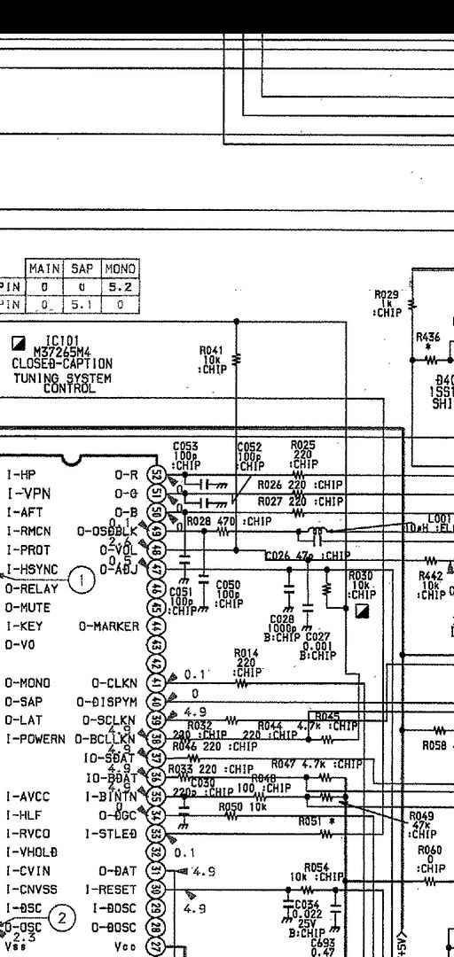
Just try with 5V first. Note I have not RGB modded a TV with this jungle, nor any with these combined blanking and color thingies. Anyway, I'd build the voltage divider with the 2.7k and the 3.9k as per the diagram, and throw 5V at it, see if it blanks. If it does, then inject red or green, and check that they work as expected, then do the blue one. A lot of this stuff is tinkering... The numbers i mention are the ones in the middle of page 4.
Curious, what do you think of this approach? Would this do the same thing? If I’m on the right track I could change values of R1 and/or R2 to modify the DC offset.

Re: TV RGB mod thread
Thank You skum.skum wrote:The original R313 10K is most likely just a current limiter (wise) so inject before that. Is R319 populated? Otherwise that's where I'd put a 10K in (the value is not that important, it's simply to avoid drawing too much current when 5V is injected). So between R313 and R319 (which if not there, add a resistor to the pads) is where your switch should simply inject 5V, basically what your drawing shows. At least that's how I'd try it if I was doing itF-Bomb wrote: Or do I just need to change 0.5v to 5v?
You can see the wiring on the third picture of my original post.
The two resistors near the black cable are the voltage divider. I can remove them. Where the 75ohm resistor goes into the board is 5v so I can put the grey wire in there.
The resistor where the black wire is attached is R313 10Kohm. I should be able to put that back into the hole where the Brown wire is.
Let me know if this is correct and I'll make the change and let you know how it goes.No guarantees made, and smoke and fire is of course to be expected
Your advice has paid off. The results are exactly what I was after.
Sorry mate, but no smoke and fire
The only thing I have to do now is move the picture about 7mm to the right in the service menu.
It also seems to have cleared up the issue I was having with the picture being a little washed out.
Here is the entire mod. (all the stuff shaded in the red area is not populated on the board). All of the BW's are 'bridging wire' (I think) and were removed and replaced with the resistors.


It's amazing. I was able to do this mod with junk and old cables I had lying around.
I took 3 x 75ohm resistors from some old PAL SNES RGB 'retro gaming cables' that I had lying around.
I also used one of these old cables as the cable from the SCART plug and switch to the board.
The S-Video and Audio Jacks were from an old SNES cable.
The 1.5Kohm resistor was from an old PS2 to JPAC cable that I had previously butchered.
The SCART plug was from one of these (below), which I cracked open and de-soldered.

All the other caps and resistors were already on the board, and instead of pulling pins etc, I searched around on the board for spare pads.
The only thing I had to buy was 2 x 2 throw single pole $3 switches. Which I ended up only using 1 of.
So for the total cost of $6 for parts and $10 for the Tv service manual (I couldn't find it for free) I now have a RGB Tv.
Thanks again skum for your help, and the entire history of the thread for the wealth of information here.
Hopefully I have contributed.
Re: TV RGB mod thread
This is prolly what I'd have started out with myself. Then when you get it blanking, try to measure the voltages on the RGB pins before injecting anything, just to verify if the numbers from the datasheet fits, if those numbers describe the DC offset maybe...SlightlyObsessed wrote: Curious, what do you think of this approach? Would this do the same thing? If I’m on the right track I could change values of R1 and/or R2 to modify the DC offset.
-
SlightlyObsessed
- Posts: 15
- Joined: Thu Apr 12, 2018 9:29 pm
Re: TV RGB mod thread
Ok I have some thoughts on the numbers that I can share here shortly.skum wrote:This is prolly what I'd have started out with myself. Then when you get it blanking, try to measure the voltages on the RGB pins before injecting anything, just to verify if the numbers from the datasheet fits, if those numbers describe the DC offset maybe...SlightlyObsessed wrote: Curious, what do you think of this approach? Would this do the same thing? If I’m on the right track I could change values of R1 and/or R2 to modify the DC offset.
Quick sanity check though please.
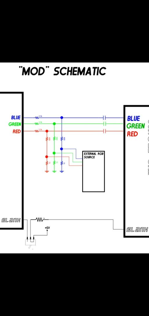
If I’m adding 5v DC in this voltage divider as pictured (to create a DC offset of the analog video signal), that extra voltage won’t be an issue for the device supplying the blue signal correct? And that is, because that .1uF cap will block DC going back towards the blue source? Just want to make sure I won’t be sending voltage back into the console.
Re: TV RGB mod thread
Yes the cap blocks DC. Most jungles usually need a cap already because there's a DC offset on the inputs. For the resistor values I'd just use the same as they do, 2.7/3.9 or whatever you got that gives somewhat the same ratio. It seems that 1.5V is mentioned some times regarding the blue pin, so I'd try to reach that value for starters.SlightlyObsessed wrote: Ok I have some thoughts on the numbers that I can share here shortly.
Quick sanity check though please.
If I’m adding 5v DC in this voltage divider as pictured (to create a DC offset of the analog video signal), that extra voltage won’t be an issue for the device supplying the blue signal correct? And that is, because that .1uF cap will block DC going back towards the blue source? Just want to make sure I won’t be sending voltage back into the console.
-
SlightlyObsessed
- Posts: 15
- Joined: Thu Apr 12, 2018 9:29 pm
Re: TV RGB mod thread
Thanks for confirmation that the DC offset won’t be making it back to the console side.skum wrote:Yes the cap blocks DC. Most jungles usually need a cap already because there's a DC offset on the inputs. For the resistor values I'd just use the same as they do, 2.7/3.9 or whatever you got that gives somewhat the same ratio. It seems that 1.5V is mentioned some times regarding the blue pin, so I'd try to reach that value for starters.SlightlyObsessed wrote: Ok I have some thoughts on the numbers that I can share here shortly.
Quick sanity check though please.
If I’m adding 5v DC in this voltage divider as pictured (to create a DC offset of the analog video signal), that extra voltage won’t be an issue for the device supplying the blue signal correct? And that is, because that .1uF cap will block DC going back towards the blue source? Just want to make sure I won’t be sending voltage back into the console.
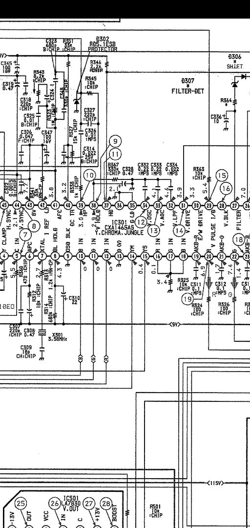
Here are my thoughts as far as the numbers go. I think I understand what the document is saying now. And I believe you were originally looking at the output of RGB on the IC and not the input pins (since you referred to the Y out DC (3-5V) numbers). Accordingly the doc and taking their average number, the average blanking level should be 0.8 and the average input for the RGB pins is 2.2 volts. Which means if the video is .7 (p-p) and a DC offset is applied at 1.5 volts all the numbers match up. (if I got all this correct).
1.5v dc offset + .7 positive video peak= their rated average value of 2.2 on the input pin.
1.5v dc offset - .7 negative video peak= 0.8 which is their value for average blanking.
So yeah, it’s still a guess but I think the DC offset needs to be 1.5v....and now that I read it over more it looks like I need to add 1.5v offset to R and B too since those specifically show “B - IN:1.5” and have the same average voltage as blue ...kinda like you were saying where the chip oven has an offset.

Re: TV RGB mod thread
Sounds right, question is though if the offset is created internally, or you have to do it. My guess is that when you offset B with 1.5V R and G will be offset also (by the chip) so you still need caps on the other lines also. This is what I'd verify first by only messing with B input, for now forgetting all video signals. Start by getting it to blank. Then measure the voltage on the R and/or G terminals. Maybe even check if there's a relation to your injected blanking voltage (like what if you add 2V instead?). Now when you know it's blanking and most likely can measure some offset on the R/G pins, add a 0.1uF cap to eg. R, and inject your red. See that it works, and then do the rest the same way.SlightlyObsessed wrote:Thanks for confirmation that the DC offset won’t be making it back to the console side.skum wrote:Yes the cap blocks DC. Most jungles usually need a cap already because there's a DC offset on the inputs. For the resistor values I'd just use the same as they do, 2.7/3.9 or whatever you got that gives somewhat the same ratio. It seems that 1.5V is mentioned some times regarding the blue pin, so I'd try to reach that value for starters.SlightlyObsessed wrote: Ok I have some thoughts on the numbers that I can share here shortly.
Quick sanity check though please.
If I’m adding 5v DC in this voltage divider as pictured (to create a DC offset of the analog video signal), that extra voltage won’t be an issue for the device supplying the blue signal correct? And that is, because that .1uF cap will block DC going back towards the blue source? Just want to make sure I won’t be sending voltage back into the console.
Here are my thoughts as far as the numbers go. I think I understand what the document is saying now. And I believe you were originally looking at the output of RGB on the IC and not the input pins (since you referred to the Y out DC (3-5V) numbers). Accordingly the doc and taking their average number, the average blanking level should be 0.8 and the average input for the RGB pins is 2.2 volts. Which means if the video is .7 (p-p) and a DC offset is applied at 1.5 volts all the numbers match up. (if I got all this correct).
1.5v dc offset + .7 positive video peak= their rated average value of 2.2 on the input pin.
1.5v dc offset - .7 negative video peak= 0.8 which is their value for average blanking.
So yeah, it’s still a guess but I think the DC offset needs to be 1.5v....and now that I read it over more it looks like I need to add 1.5v offset to R and B too since those specifically show “B - IN:1.5” and have the same average voltage as blue ...kinda like you were saying where the chip oven has an offset.
-
SlightlyObsessed
- Posts: 15
- Joined: Thu Apr 12, 2018 9:29 pm
Re: TV RGB mod thread
Sounds like a plan...now if I only had the .1 uF caps to get started. I dug through all my spares parts and came up empty there...going to have to place an orderskum wrote:
Sounds right, question is though if the offset is created internally, or you have to do it. My guess is that when you offset B with 1.5V R and G will be offset also (by the chip) so you still need caps on the other lines also. This is what I'd verify first by only messing with B input, for now forgetting all video signals. Start by getting it to blank. Then measure the voltage on the R and/or G terminals. Maybe even check if there's a relation to your injected blanking voltage (like what if you add 2V instead?). Now when you know it's blanking and most likely can measure some offset on the R/G pins, add a 0.1uF cap to eg. R, and inject your red. See that it works, and then do the rest the same way.
-
SonyTrinitron32HV600
- Posts: 2
- Joined: Mon Mar 30, 2020 3:02 am
Re: TV RGB mod thread
I acquired this CRT 5 days ago via a curb find on my street and want to attempt to RGB mod it and need some assistance.
This will be my first attempt, so i will need a lot of help. if someone could download the service manual and use microsoft paint to circle and trace what i need to pay attention too, that would help a lot.
I'm decent at soldering, so that isn't an issue. The TV has 2 RGB In points, because it has a composite on the back and on the left side of the TV. I want to see if i can apply a RGB mod on one point, so i can still have my OSD intact.
https://elektrotanya.com/apex_at2002_ch ... nload.html
https://datasheetspdf.com/pdf-file/6030 ... /LA76814/1
https://datasheetspdf.com/datasheet/LA76814.html
http://www.ic72.com/pdf_file/l/130175.pdf
Re: TV RGB mod thread
For now basically any cap can do. If you got 1uf, use those.SlightlyObsessed wrote:Sounds like a plan...now if I only had the .1 uF caps to get started. I dug through all my spares parts and came up empty there...going to have to place an orderskum wrote:
Sounds right, question is though if the offset is created internally, or you have to do it. My guess is that when you offset B with 1.5V R and G will be offset also (by the chip) so you still need caps on the other lines also. This is what I'd verify first by only messing with B input, for now forgetting all video signals. Start by getting it to blank. Then measure the voltage on the R and/or G terminals. Maybe even check if there's a relation to your injected blanking voltage (like what if you add 2V instead?). Now when you know it's blanking and most likely can measure some offset on the R/G pins, add a 0.1uF cap to eg. R, and inject your red. See that it works, and then do the rest the same way.
-
UltimaN3rd
- Posts: 1
- Joined: Tue Apr 07, 2020 2:53 pm
Re: TV RGB mod thread
I'm looking at a Sanyo DS19630 and having a bit of trouble. The jungle chip is LA7673: 
As you can see, there are R/G inputs into the jungle, but the B is apparently both Blue and Blank. . . Does this mean that either the entire screen would have to be blue (along with the red/green signals) in order to display the full image, or that the RGB inputs would only show up when the Blue signal is active? Pretty strange but does anyone know if this could be worked around to get a proper RGB input going or is this TV a lost cause?
Cheers.
Re: TV RGB mod thread
I’m been working on the Samsung TV that I mentioned in my previous post. When ever I blank it I just get a white screen that goes away when I disconnect the composite sync. Perhaps it’s not really blanking and just picking up the composite sync which causes the white screen? I’ve tried from 2.5 volts to 5 volts for blanking and it makes no difference. Does anyone know what the issue my be? Is there a way to do a search just within this thread? Any input is greatly appreciated, thanks.
-
Ilike2drive
- Posts: 4
- Joined: Wed Apr 08, 2020 8:55 pm
Re: TV RGB mod thread
Hi, looking for a little help with the best way to mod my kv20m10. I have a picture of a setup I was going to replicate and schematics. Just unsure what to do with R025, R026, R027. I have 75ohm resistors and .1uf caps I was going to add going from the scart cable .
Re: TV RGB mod thread
I had this same problem, got a spongebob tv with plans to copy the mod the other guy did the writeup on but never got it working. blew it up now so....nes.og wrote:I’m been working on the Samsung TV that I mentioned in my previous post. When ever I blank it I just get a white screen that goes away when I disconnect the composite sync. Perhaps it’s not really blanking and just picking up the composite sync which causes the white screen? I’ve tried from 2.5 volts to 5 volts for blanking and it makes no difference. Does anyone know what the issue my be? Is there a way to do a search just within this thread? Any input is greatly appreciated, thanks.
I got a trinitron with a well know jungle that looks really easy to mod. Just gonna do the switch mod, keep it simple hopefully this one works.
-
darthcloud

- Posts: 131
- Joined: Mon May 22, 2006 11:44 pm
- Location: Canada
Re: TV RGB mod thread
Refined my JVC mod by using the CVBS input share with the S-Video one for CSYNC. This allow to keep the 2nd input free for a composite input. And using a DPDT switch I can toggle between the RGB and S-Video plug for VIDEO1 input.
Made a small blog post about it:
https://hackaday.io/project/170807-dart ... rt-rgb-mod
Somehow got feature on the main hackaday page!
https://hackaday.com/2020/04/09/adding-rgb-to-a-crt/
Made a small blog post about it:
https://hackaday.io/project/170807-dart ... rt-rgb-mod
Somehow got feature on the main hackaday page!
https://hackaday.com/2020/04/09/adding-rgb-to-a-crt/
Re: TV RGB mod thread
I have a Toshiba MD20Q42, which I'm trying to mod both RGB and S-Video onto. I'm not sure the S-Video will work like this, since the DVD player uses the Luma and Chroma inputs. How does this look?

Re: TV RGB mod thread
Finally some success! Picked up a Trinitron kv-27fs210, a lot bigger than I wanted but it has a through-hole jungle that other people have had success with. I wired it up and I have a picture! the colors are way off but something is happening!


Not sure why the color is so strange, maybe the RGB line levels are too high? The 360 ohm resistors were originally part of a mixing circuit but I decided do do the simpler switch circuit because I just wanted to see something work before I try any tricky stuff.
Not sure why the color is so strange, maybe the RGB line levels are too high? The 360 ohm resistors were originally part of a mixing circuit but I decided do do the simpler switch circuit because I just wanted to see something work before I try any tricky stuff.
-
SlightlyObsessed
- Posts: 15
- Joined: Thu Apr 12, 2018 9:29 pm
Re: TV RGB mod thread
UPDATES and QUESTIONS:
I haven't had much luck with the LA7672 (it has blue and blanking on the same input). I was able to get it blanking but when applying video to any pin including the combined blank/blue pin the tube gives no joy.
I decided to switch gears and try something easier to start (hopefully). I picked up a Panasonic CT-27DC50B but haven’t been able to find a service manual.
It has a AN5166k jungle chip, I’ve found a basic diagram here:
https://es.datasheetq.com/view.jsp?pn=A ... =Panasonic
The AN5165K seems similar and I can find a more proper data sheet here:
https://industrial.panasonic.com/conten ... discon.pdf
The good news is I achieve blanking via 5v to pin 3. I’ve pulled jumper wires that went to RBG-in pins 4,5,6 and am injecting video directly there (no muxing, just trying to prove it works for now). I couldn’t get any picture unless I remove the cap (1uf or .47uf is all I have ATM). Doing that, I get picture but the image gradually gets darker until faint or black (within seconds). The picture stays on longer if I remove the 75 ohm terminating resistors too but not much longer. I noticed a few other posts in the thread with the same or similar ICs where people mentioned similar results but didn’t read any possible solutions. Any thoughts or suggestions would be appreciated!
Re: TV RGB mod thread
I figured out why the picture looked so strange, I had the red and green lines swapped.
Re: TV RGB mod thread
Well I started down the path of modifying a TV for RGB. The MiSTer project has me hooked. I have a smaller PVM that is great but I would like a 19" TV to play on. I had a TV saved for a project or a Donor tube for one of my arcade machines. This thead has me excited to convert a TV to RGB. This TV is RF only so I am wondering if in the 99 pages of this thread if anyone has successfully modded one without composite already on it?
Here is the Tube I have:
Magnavox/Philips 19PRC1 0121
Chassis Board: 19G601-00AA
1. I am having trouble finding the service manual for this TV. Any suggestions?
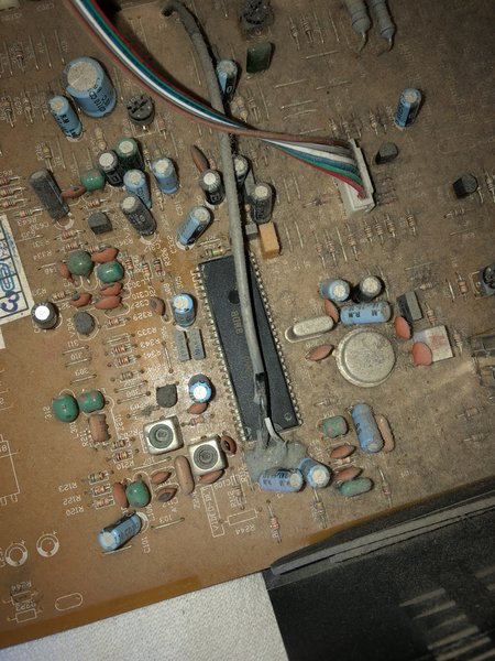
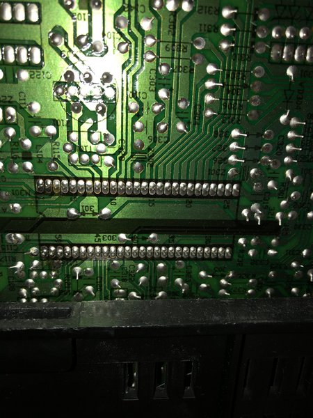
2. Which one is my Jungle Chip? I've taken a picture of the board on both sides?
3. Where do you think I can pull c-sync from?
Here are the pics: https://drive.google.com/open?id=1fwwH3 ... CHBy8sxUOA
This would be an RGB only tube so I don't mind "no turning back" modifications
Here is the Tube I have:
Magnavox/Philips 19PRC1 0121
Chassis Board: 19G601-00AA
1. I am having trouble finding the service manual for this TV. Any suggestions?
2. Which one is my Jungle Chip? I've taken a picture of the board on both sides?
3. Where do you think I can pull c-sync from?
Here are the pics: https://drive.google.com/open?id=1fwwH3 ... CHBy8sxUOA
This would be an RGB only tube so I don't mind "no turning back" modifications
Re: TV RGB mod thread
I also got a Philips 20 inch with a TDA9377 in it that I am hoping I can pass it RGB in through the RGBIN pins. Did anyone ever get that working?

Re: TV RGB mod thread
I'm getting some interference on the rgb wires, tried moving them around and things got better but i think I will buy some shielded wire and put a 4 pole solid state relay or something near the chip to avoid having these wires running everywhere picking up noise.
Also, my picture is a little too far left, any idea what causes that?
+
Also, my picture is a little too far left, any idea what causes that?
+

Re: TV RGB mod thread
flynnsbit wrote:I also got a Philips 20 inch with a TDA9377 in it that I am hoping I can pass it RGB in through the RGBIN pins. Did anyone ever get that working?
That jungle ic looks just like the one on my Philips,it's software locked to only rgb or component.
Re: TV RGB mod thread
Anyone fiddled with intercepting I2C and change appropriately?Pikkon wrote:That jungle ic looks just like the one on my Philips,it's software locked to only rgb or component.flynnsbit wrote:I also got a Philips 20 inch with a TDA9377 in it that I am hoping I can pass it RGB in through the RGBIN pins. Did anyone ever get that working?
Re: TV RGB mod thread
They are an all in one chip.skum wrote:Anyone fiddled with intercepting I2C and change appropriately?
___________________________________________________
MarkOZLAD
OSD/External RGB Mux Diagram
OSD/External RGB Mux Resistor Value Table 0.7Vp-p : 0.5Vp-p
"Imagine toggle switch OSD modding a TV in 2019" - maxtherabbit
MarkOZLAD
OSD/External RGB Mux Diagram
OSD/External RGB Mux Resistor Value Table 0.7Vp-p : 0.5Vp-p
"Imagine toggle switch OSD modding a TV in 2019" - maxtherabbit
Re: TV RGB mod thread
Ah those... I missed that, as I've usually seen them in TQFP packages, so the picture threw me off. Sad :/MarkOZLAD wrote:They are an all in one chip.skum wrote:Anyone fiddled with intercepting I2C and change appropriately?
-
CrashFan96

- Posts: 3
- Joined: Tue Apr 14, 2020 11:22 am
Re: TV RGB mod thread
Hi, I have a Konka Model K1398U CRT tv, so is it possible to RGB mod it?
https://atariage.com/forums/uploads/mon ... 980a0.jpeg
https://atariage.com/forums/uploads/mon ... bb936.jpeg
https://atariage.com/forums/uploads/mon ... bbee2.jpeg
https://atariage.com/forums/uploads/mon ... 152a5.jpeg
https://atariage.com/forums/uploads/mon ... 3ba80.jpeg
https://atariage.com/forums/uploads/mon ... 5f1e0.jpeg
https://atariage.com/forums/uploads/mon ... ef2f0.jpeg
https://atariage.com/forums/uploads/mon ... 8cf22.jpeg
Re: TV RGB mod thread
flynnsbit wrote:Well I started down the path of modifying a TV for RGB. The MiSTer project has me hooked. I have a smaller PVM that is great but I would like a 19" TV to play on. I had a TV saved for a project or a Donor tube for one of my arcade machines. This thead has me excited to convert a TV to RGB. This TV is RF only so I am wondering if in the 99 pages of this thread if anyone has successfully modded one without composite already on it?
Here is the Tube I have:
Magnavox/Philips 19PRC1 0121
Chassis Board: 19G601-00AA
1. I am having trouble finding the service manual for this TV. Any suggestions?
2. Which one is my Jungle Chip? I've taken a picture of the board on both sides?
3. Where do you think I can pull c-sync from?
Here are the pics: https://drive.google.com/open?id=1fwwH3 ... CHBy8sxUOA
This would be an RGB only tube so I don't mind "no turning back" modifications
The jungle is the one on the "Top.jpg" shot near the bottom of the photo with the half shield on it. IC270.
Before modding an RF only set you need to determine if it is a live chassis set. If it is you will need an isolation transformer or some other option to make sure it doesn't short to ground through the external device you attach to it.
___________________________________________________
MarkOZLAD
OSD/External RGB Mux Diagram
OSD/External RGB Mux Resistor Value Table 0.7Vp-p : 0.5Vp-p
"Imagine toggle switch OSD modding a TV in 2019" - maxtherabbit
MarkOZLAD
OSD/External RGB Mux Diagram
OSD/External RGB Mux Resistor Value Table 0.7Vp-p : 0.5Vp-p
"Imagine toggle switch OSD modding a TV in 2019" - maxtherabbit
Re: TV RGB mod thread
Great to see that even a man of your massive talents has stuff to learn Mr Skumskum wrote:Ah those... I missed that, as I've usually seen them in TQFP packages, so the picture threw me off. Sad :/MarkOZLAD wrote:They are an all in one chip.skum wrote:Anyone fiddled with intercepting I2C and change appropriately?
___________________________________________________
MarkOZLAD
OSD/External RGB Mux Diagram
OSD/External RGB Mux Resistor Value Table 0.7Vp-p : 0.5Vp-p
"Imagine toggle switch OSD modding a TV in 2019" - maxtherabbit
MarkOZLAD
OSD/External RGB Mux Diagram
OSD/External RGB Mux Resistor Value Table 0.7Vp-p : 0.5Vp-p
"Imagine toggle switch OSD modding a TV in 2019" - maxtherabbit