TV RGB mod thread

The place for all discussion on gaming hardware
XeD
Posts: 10
Joined: Wed Mar 01, 2017 6:28 pm

Re: TV RGB mod thread

Post by XeD »

Syntax wrote:You'll usually see something for h sync and v sync separate
Just for my understanding, this jungle ic is ttl?
https://klovimg.com/image/3w9Ld
https://klovimg.com/image/3witg
User avatar
Josh128
Posts: 2142
Joined: Thu Jan 16, 2014 9:01 am

Re: TV RGB mod thread

Post by Josh128 »

lukilla wrote:I was thinking that those JVC aren´t for me, GDI (samsung?) tube is nice but not as good as others I´ve used, so just got this with very little usage and modded by the naughty method, no other option for them anyway :lol:

The power of two 8)

Image


These like 2.7kohm in series, very little dust inside.-

Image


Simple vga socket.-

Image


Image


Voilá.-

Image
Image
Image
Lukilla-- is that MAME Final Fight running in 240p? If so, may I ask how you managed that?
lukilla
Posts: 66
Joined: Fri Apr 14, 2017 2:21 am

Re: TV RGB mod thread

Post by lukilla »

I use a gtx950 with custom resolutions via the nvidia control panel, final fight is running @384x224.
User avatar
buttersoft
Posts: 383
Joined: Sun Jul 24, 2016 7:49 am

Re: TV RGB mod thread

Post by buttersoft »

Josh128 wrote:Lukilla-- is that MAME Final Fight running in 240p? If so, may I ask how you managed that?
!What's the question? Final Fight runs great at 240p...? You just set MAME to output that way, or GM if you're using it.


Lukilla, what steps did you take to get 240p out of the NVCP? Every time i've tried on my 980ti it just refuses to output it. Are you literally just adding a resolution and that's it, no other programs or settings?
lukilla
Posts: 66
Joined: Fri Apr 14, 2017 2:21 am

Re: TV RGB mod thread

Post by lukilla »

I´ve had no problem using only the nvcp (win7 and win10). Below is an example:

https://i.imgur.com/GCO4AFd.png
User avatar
Josh128
Posts: 2142
Joined: Thu Jan 16, 2014 9:01 am

Re: TV RGB mod thread

Post by Josh128 »

I didnt realize modern GPUs allowed for 15Khz output, but I guess Im still thinking of when they would output in component/Svideo/Composite-- there was no way to force them to output 15Khz.

How are you getting C-Sync from the VGA, are you using some kind of circuit to combine the H and V?

*Nevermind, from the pics I can see you are using both H and V Sync.....Im assuming the remaining wire is the ground?
lukilla
Posts: 66
Joined: Fri Apr 14, 2017 2:21 am

Re: TV RGB mod thread

Post by lukilla »

You are limited to vga output for 15khz. For sync combining I use Tim´s dodgy diode circuit:

Image
User avatar
Syntax
Posts: 1776
Joined: Wed Aug 09, 2017 12:10 am
Location: Australia

Re: TV RGB mod thread

Post by Syntax »

Found another LG set that wont accept csync when modded. It seems the later models incorporated a sensing switch that sees csync as luma and goes into svideo mode.

This particular set (RT-21FA31) can do component composite s video and rgb BUT only component OR RGB not both.

It has an inbuilt osd in the jungle so it ended up being a component hack instead of an osd one.

Heres a picture of my work on it

https://i.imgur.com/sBod4Df.jpg
Last edited by Syntax on Sun Jan 14, 2018 2:37 am, edited 2 times in total.
XeD
Posts: 10
Joined: Wed Mar 01, 2017 6:28 pm

Re: TV RGB mod thread

Post by XeD »

Syntax wrote:Found another LG set that wont accept csync when modded. It seems the later models incorporated a sensing switch that sees csync as luma and goes into svideo mode.

This particular set (RT-21FA31) can do component composite s video and rgb BUT only component OR

It has an inbuilt osd in the jungle so it ended up being a comonent hack instead of an osd one.

Heres a picture of my work on it

https://i.imgur.com/sBod4Df.jpg
Can you enlighten me on what the comonent hack is?
User avatar
Syntax
Posts: 1776
Joined: Wed Aug 09, 2017 12:10 am
Location: Australia

Re: TV RGB mod thread

Post by Syntax »

The sets chassis is only setup for RGB or Component.

They have different part values for their signal line but same part location if that makes sense.

Component goes through an rgsb matrix and scart has to bypass that but cannot without stuffing with component.

So just like an OSD hack the component lines are cut just before the jungle.

**edit** straight over my head lol. I thought i fixed that typo. Stupid thumbs 4 times the size of my screen keys.
User avatar
Josh128
Posts: 2142
Joined: Thu Jan 16, 2014 9:01 am

Re: TV RGB mod thread

Post by Josh128 »

lukilla wrote:You are limited to vga output for 15khz. For sync combining I use Tim´s dodgy diode circuit:

Image
Thanks, another dumb question though-- once this mod is done, I assume input switching via OSD are no longer possible? Also, can it accept audio at the same time as VGA? Sorry for all the questions, but I find these mods very interesting and am fairly clueless about them. I have an old Sanyo 32" with S-Video and composite in that has a very nice screen with deep blacks. Would not mind attempting something like this. For a set like that do you think direct wiring would be the way to go or does it contain a jungle chip that could be modded?
lukilla
Posts: 66
Joined: Fri Apr 14, 2017 2:21 am

Re: TV RGB mod thread

Post by lukilla »

To use osd you would need to make a switch, vga and audio are different signals so it doesn´t matter. As for your tv you would need to find the service manual online and post an image of the jungle ic for us to see :D
User avatar
Syntax
Posts: 1776
Joined: Wed Aug 09, 2017 12:10 am
Location: Australia

Re: TV RGB mod thread

Post by Syntax »

viletim wrote:
mikejmoffitt wrote:In the OP I made a diagram showing how to do a switched OSD injection.

For the YSW signal, if you are using SCART, you might be able to create this logic:

YSW <= OSD_YSW || SCART_5V

You can look into analogue signal switches to use the OSD_YSW to switch between your injected RGB and the original OSD RGB.
mikejmoffitt wrote: With no second RGB / teletext input; injecting using OSD lines:
Image

* Snip-snap the internal OSD RGB signals going into the jungle mixer
* Inject your RGB there instead, with 75 ohm resistors to ground and then a ~0.1uF capacitor in series to the RGB input
* Pull the jungle mixer blanking pin out of circuit, and tie it high (nearby jungle VCC, usually 3.3~5V) to make it always blanking (always showing RGB)
* Put your composite sync signal into an available luma input (or composite if that's all you have)
* Put that noise on a switch so you can change it back and forth
* Enjoy RGB

I found a low cost TV design that fudges the OSD and SCART input together like this. I think it's the best implementation I've seen. Here's the manual http://etim.net.au/temp/forum/DAEWOO%20 ... V%20SM.pdf (see page 64 of the PDF)

You need to have a resistor in series with the RGB signals. This is because the new termination resistors (75 ohm) in parallel with the RGB video source (75 ohm) makes a load of 37.5 ohms on the RGB input from the OSD signal's point of view. This Daewoo TV puts 150 ohm resistors in series which lifts the load on the OSD signal. Too little or no series resistance = high loading (attenuation) of the OSD, too much series resistance = poor clamp performance. It's a compromise. 150 ohms looks like a good choice to me. The other important part is the RGB OSD signals must each have diodes in series. This way they are effectively out of the circuit when it's off. This prevents loading of the RGB input. An emitter follower + diode OR circuit combines the fast blanking from SCART with the fast blanking of the OSD.
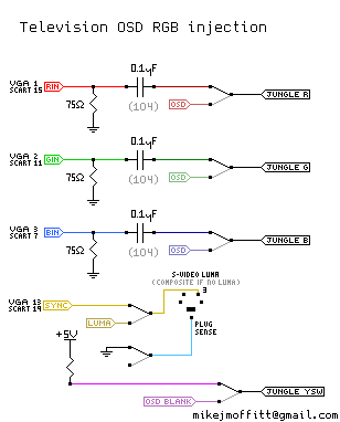
You got me thinking about the 75ohm termination in the tv set adding to the console terminations so I pulled out the multimeter and check some systems

I just checked the RGB lines to ground on 3 consoles for the resistance values.

N64RGB board (Tims)
R= 20k
G= 150 ohm <-------WHY??? I checked with the system off, no scart cable ect.
B= 20k

On my Snes mini RGB bypass(Bortis)
R= 20k
G= 20k
B= 20k

On my RGBNES(Tims)
R= 7meg
G= 6meg
B= 7meg

I can understand something like a normal snes console with 75ohm resistors in the scart head would end up with 37.5 ohms but it doesn't seem to be a solution for every scenario.

Wait I think as I type this I'm under standing. If you don't have a console that outputs 75ohm terminations, or you don't have a console in, the OSD will see 150+75=225ohm termination.
But then you plug a console in and your 75 drops to 37.5 something so now your OSD sees a 187.5 ohm termination.
Not really a big jump in attenuation but it still seems strange.

With your Daewoo set, with a console that has 75 ohm terminations, the OSD is 0.58vpp.
With a console without 75 ohm terminations the OSD is 0.68vpp

I've worked on LG sets with 1k inlines.
If you use a 5.6k on the osd before the diode then

console with 75 ohm terminations OSD= 0.67vpp
console without 75 ohm terminations OSD= 0.69vpp

Far less variation.
User avatar
buttersoft
Posts: 383
Joined: Sun Jul 24, 2016 7:49 am

Re: TV RGB mod thread

Post by buttersoft »

lukilla wrote:I´ve had no problem using only the nvcp (win7 and win10). Below is an example:

https://i.imgur.com/GCO4AFd.png
Cheers, i'll take a look.

My next question is why are you using 320x224 for Final fight when the CPS1 system outputs 384x224? :) Or was that merely a random 15kHz progressive mode you grabbed, not the one you use for FF?
lukilla
Posts: 66
Joined: Fri Apr 14, 2017 2:21 am

Re: TV RGB mod thread

Post by lukilla »

Nope, FF is on a different resolution.
MarkOZLAD
Posts: 1004
Joined: Thu May 18, 2017 12:39 pm

Re: TV RGB mod thread

Post by MarkOZLAD »

So Syntax and I have been working on a way to perform the RGB mods on sets that usually require an OSD snip and a switch by instead muxing the OSD and external RGB.

Syntax was able to successfully perform this task this week on a Sanyo CP14SW1. Service manual here

I had previously had some success with an NEC TV but there were issues with the termination of RGB/OSD and then Tim posted about a TV chassis that muxed the OSD and RGB together. We went about studying Tim's post and the maths of the circuit he described. Obviously this stuff is easy for Tim but us layman (hacks?) had to take a bit of time to digest it.

Here is the schematic of the circuit we came up with to mux the External RGB and OSD RGB.

Schematic

There are two main concepts in play for the RGB.

Firstly the diodes on the OSD RGB lines isolate the External RGB lines from the OSD resistors. Normally the sets have a voltage divider on the OSD RGB lines which interfere with the 75Ohm termination of the external RGB lines if we just join them.

Secondly the inline resistors (the 5.6K on the OSD lines the 1K's on the External RGB lines) plus the 75 ohm Termination resistors of the external RGB lines act as the "R1" and "R2" of a voltage divider for the OSD lines. The OSD lines are 5V point to point. The voltage divider + the diode bring the OSD RGB voltages down to 0.7V point to point.

Ignoring any 75 ohm termination in the console the maths for working out the resultant OSD lines is:

(Source Voltage - Diode Voltage Drop) * (Second Inline Resistor + Terminating Resistor)/(First In line Resistor + Second Inline Resistor + Terminating Resistor)

(5.0V - 0.7V) * (1000 + 75) / (5600 + 1000 + 75) = 0.69V

If we take into account terminating resistors on the console side:

(5.0V - 0.7V) * (1000 + (75 *75)/(75+75) ) / (5600 + 1000 + (75 *75)/(75+75)) = 0.67V

Either way we get very close to the standard 0.7V p-p that we expect at the Jungle.

The results aren't perfect. Syntax still thinks the OSD is a bit washed out during RGB insertion but it is definitely usable.

Here is a video of the TV in action.

If you're wondering about the choice of the 1k inline resistor on the external RGB lines, we tested a few options but realised the maths favoured larger resistors (for power dissipation and for OSD voltage variation when attaching consoles that do or don't have 75 ohm termination). We have both worked on LG MC-84a chassis before and they have 1k inline resistors on the external RGB lines so Syntax gave it a try. In fact he tried values up to 10K and the ext RGB clamping seemed unaffected.

Oh, for the blanking circuit, Syntax came up with this quickly. We still haven't taken the time to understand the blanking mechanism Tim mentioned in his post. We understand that this is debatable (of course everything here is)
Last edited by MarkOZLAD on Mon Jan 29, 2018 12:52 am, edited 1 time in total.
___________________________________________________
MarkOZLAD
OSD/External RGB Mux Diagram
OSD/External RGB Mux Resistor Value Table 0.7Vp-p : 0.5Vp-p

"Imagine toggle switch OSD modding a TV in 2019" - maxtherabbit
fandangos
Posts: 144
Joined: Tue Sep 18, 2012 3:48 am

Re: TV RGB mod thread

Post by fandangos »

The sony set I modded earlier (kv-29fv305) don't care about external blanking for OSD.
It has a diode and I went 5v after the diode.
If I leave both rgb lines together and blanking on and I press menu I can see the OSD very faint.

So if I use this circuit of yours and leave blanking on I'll have the osd fine I suppose but I'll loose all the other inputs.


Also syntax, remeber l2fill? Found out that almost every sony set has a s501 and s502 swtch horizontal position and it's not documented in the service manual.
User avatar
Syntax
Posts: 1776
Joined: Wed Aug 09, 2017 12:10 am
Location: Australia

Re: TV RGB mod thread

Post by Syntax »

fandangos wrote: Also syntax, remeber l2fill? Found out that almost every sony set has a s501 and s502 swtch horizontal position and it's not documented in the service manual.

Very interesting, care to shed some more light on the matter?
fandangos
Posts: 144
Joined: Tue Sep 18, 2012 3:48 am

Re: TV RGB mod thread

Post by fandangos »

Syntax wrote:
fandangos wrote: Also syntax, remeber l2fill? Found out that almost every sony set has a s501 and s502 swtch horizontal position and it's not documented in the service manual.

Very interesting, care to shed some more light on the matter?
Not yet. As you know my sony even with Hpos at 0 has a black bar on the left side and I can expand but the image is not centralized.
I've found a really old post in a brazilian forum of someone just saying you can tweak s501 and s502 and the person just said he was going to get another wega tv.

So I googled it and it's present on my chassis the BA-5D and on a ton of other sony models.
It's a switch on the horizontal out and it changes from a resistor to another but it's not a pot.

I'm going home friday and I'm really excited to try it out and get back with some positive news.
User avatar
Syntax
Posts: 1776
Joined: Wed Aug 09, 2017 12:10 am
Location: Australia

Re: TV RGB mod thread

Post by Syntax »

White plastic switch with a black base?
Like the Fat Controllers lever?

Always wondered what that was for.
User avatar
cyborc
Posts: 308
Joined: Wed Mar 25, 2009 6:26 am
Location: USA

Re: TV RGB mod thread

Post by cyborc »

to anyone who has RGB modded a Sony KV-27S42: Does it have any issues handling csync? I've read some posts recently about certain consumer Trinitrons not handling csync well or at all. I don't really want to waste my time modding this TV if it ends up having csync issues, because I need csync for my extron switch.
User avatar
nakedarthur
Posts: 218
Joined: Tue Jul 21, 2015 8:20 pm

Re: TV RGB mod thread

Post by nakedarthur »

cyborc wrote:to anyone who has RGB modded a Sony KV-27S42: Does it have any issues handling csync? I've read some posts recently about certain consumer Trinitrons not handling csync well or at all. I don't really want to waste my time modding this TV if it ends up having csync issues, because I need csync for my extron switch.
Don't worry, I have a bunch of consoles all using csync on it. Just run your csync into the S-video Luma and you are set.
XeD
Posts: 10
Joined: Wed Mar 01, 2017 6:28 pm

Re: TV RGB mod thread

Post by XeD »

I'm rgb nodded a Toshiba 27A4IC and I seem to have a sync issue.
https://klovimg.com/image/3QITZ
Any ideas?
User avatar
cyborc
Posts: 308
Joined: Wed Mar 25, 2009 6:26 am
Location: USA

Re: TV RGB mod thread

Post by cyborc »

nakedarthur wrote:
cyborc wrote:to anyone who has RGB modded a Sony KV-27S42: Does it have any issues handling csync? I've read some posts recently about certain consumer Trinitrons not handling csync well or at all. I don't really want to waste my time modding this TV if it ends up having csync issues, because I need csync for my extron switch.
Don't worry, I have a bunch of consoles all using csync on it. Just run your csync into the S-video Luma and you are set.
Awesome, thanks! Those pics you posted of your set a while back is the reason I tracked down an S42!
MarkOZLAD
Posts: 1004
Joined: Thu May 18, 2017 12:39 pm

Re: TV RGB mod thread

Post by MarkOZLAD »

XeD wrote:I'm rgb nodded a Toshiba 27A4IC and I seem to have a sync issue.
https://klovimg.com/image/3QITZ
Any ideas?
Any more details?
___________________________________________________
MarkOZLAD
OSD/External RGB Mux Diagram
OSD/External RGB Mux Resistor Value Table 0.7Vp-p : 0.5Vp-p

"Imagine toggle switch OSD modding a TV in 2019" - maxtherabbit
XeD
Posts: 10
Joined: Wed Mar 01, 2017 6:28 pm

Re: TV RGB mod thread

Post by XeD »

I remove the jumper W802, 808, 813 and solder my rgb line to the jungle chip side. Remove jumper W820 and solder jungle chip side to pin 2 for 5v. Seem like I'm getting a picture but with a vertical roll. I took the sync from the video 1 composit, roll. Took it from svideo same thing roll
MarkOZLAD
Posts: 1004
Joined: Thu May 18, 2017 12:39 pm

Re: TV RGB mod thread

Post by MarkOZLAD »

XeD wrote:I remove the jumper W802, 808, 813 and solder my rgb line to the jungle chip side. Remove jumper W820 and solder jungle chip side to pin 2 for 5v. Seem like I'm getting a picture but with a vertical roll. I took the sync from the video 1 composit, roll. Took it from svideo same thing roll
What is the external device?

If you plug just the sync into the AV port what do you see?
___________________________________________________
MarkOZLAD
OSD/External RGB Mux Diagram
OSD/External RGB Mux Resistor Value Table 0.7Vp-p : 0.5Vp-p

"Imagine toggle switch OSD modding a TV in 2019" - maxtherabbit
User avatar
Syntax
Posts: 1776
Joined: Wed Aug 09, 2017 12:10 am
Location: Australia

Re: TV RGB mod thread

Post by Syntax »

Looks like a pc with incorrect sync.

With these mods you either get sync, or you dont.

Shitty sync will be on the pc end of things i bet.
XeD
Posts: 10
Joined: Wed Mar 01, 2017 6:28 pm

Re: TV RGB mod thread

Post by XeD »

I don't own any retro console so all I have to test on is arcade hardware. The only thing I didn't do is the 75ohm on the run line (have to pick some up still) I won't be able to work on this again until next Wednesday :(
User avatar
Syntax
Posts: 1776
Joined: Wed Aug 09, 2017 12:10 am
Location: Australia

Re: TV RGB mod thread

Post by Syntax »

Oh snap your using a capcom board? Sorry, usually when i see third strike its a pc. Nice.

Sync might be alittle high and need attenuation.
Post Reply