i looked through this thread and i only found a couple of people talking about it. the information i did find said that this TV doesn't accept MUX modding. i don't care too much about the MUX side of things; a simple mod will work for me. here is where i need some help.
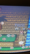
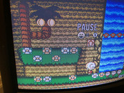
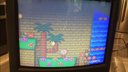
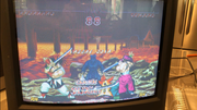
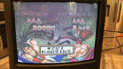
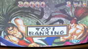
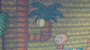
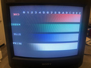
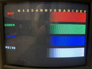
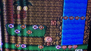
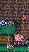
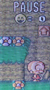
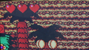
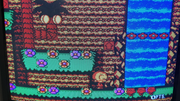
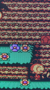
i was able to mod my set to a point. i get a nice sharp screen synced and everything, but the screen is kind of dark, like the contrast is not adjusted correctly. i have included some photos of what i see after the mod. it kind of reminds me of what an RGB signal looked like coming from a PC Engine or Turbografx 16 without an RGB amp, but this is worse.

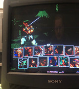
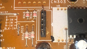
the way i modded this was by tapping the RGB in lines to the jungle chip. when i used .1uf caps and 75ohm resistors; like the basic mod, the screen hardly showed anything. but if i simply inject the RGB signal without anything added the picture looks better. while messing with it, i noticed, right next to the jungle chip, there are some open vias with an arrow pointing to them and they are labeled RGB and BLK in. i soldered some header pins into it and checked the signal, it was exactly the same as when i soldered directly to the jungle chip!
at this point, i am assuming that there are some resistors i probably need to remove or swap out to get the screen brighter, but i don't quite have the schematic reading abilities to know how to look for this. any help would be GREATLY APPRECIATED!!! i have had this TV for a while in this current state and i am anxious to hopefully get this one done.
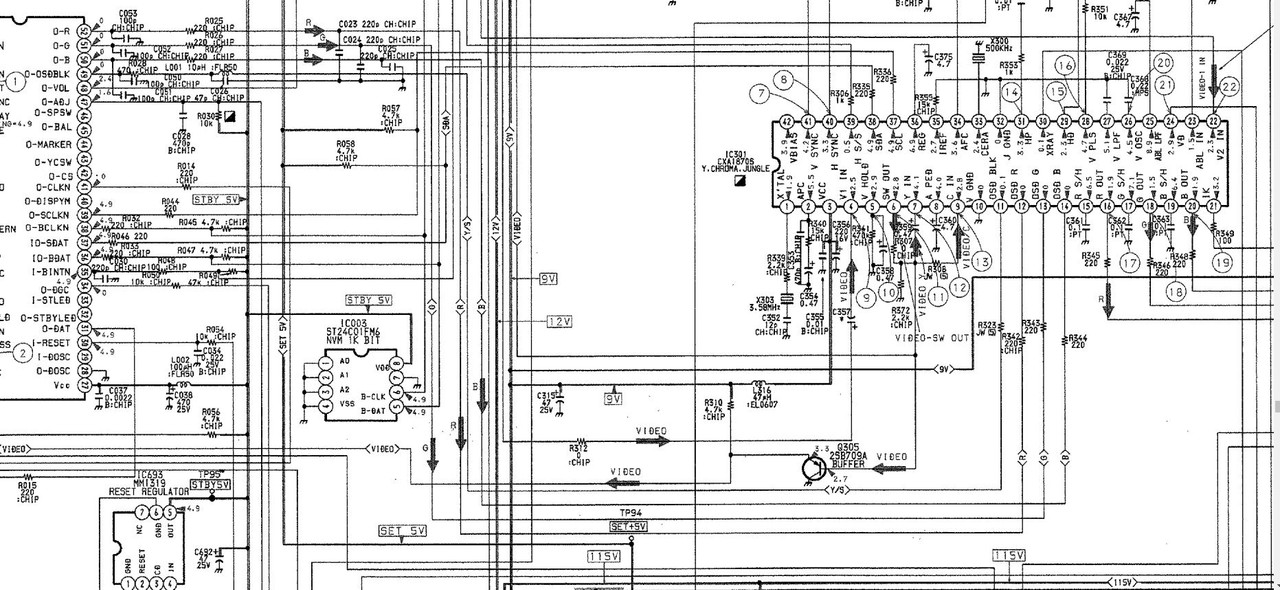
i included a schematic blow up of the route between the OSD chip and the Jungle chip in the next post.


