Disconnect the remote phono jack from the PCB, and solder a jumper to your sync line.Akuji wrote:Hey everyone! I've been thinking about a TV mod that isn't technically an RGB mod, but bare with me.
I own a PVM-14N6U and I was wondering if there was a way that I could modify the REMOTE connector phono jack (which is pretty much useless to me) to instead be an RGB "external sync out" phono jack for use with lightguns like the GunCon 2. Ideally it'd be nice if the sync corresponded to whatever input is currently being displayed on the TV, but that's complicated and in reality I'd only really need it to be for the RGB input, since Line A already has video out.
How would I go about doing this correctly? This is a very pointless mod considering you can just use rca splitter adapters to connect the lightgun instead, but I figured that it would be a cleaner and faster way to connect my lightgun seamlessly and to make use of a plug that otherwise goes unused. I'm also assuming that it shouldn't be that difficult, but I don't really know that.
TV RGB mod thread
Re: TV RGB mod thread
-
Issac Zachary
- Posts: 163
- Joined: Mon Oct 23, 2017 2:54 pm
Re: TV RGB mod thread
Time to mod!
Unused RBG input on Jungle. So, unless someone tells me otherwise, I'm thinking of trying those unused RGB inputs (pins #25-28) and if that doesn't work, then trying the used inputs with a MUX mod.
Would a 75ohm resistor from Scart to ground and 0.1u (or should I try 0.01u?) from Scart to Jungle be a good place to start?
I'm looking to hook up MiSTer and PS2.
The TV in question is a Sony KV27V40. Service Manual is here:
https://www.manualslib.com/manual/48107 ... =35#manual
Thanks for any comments or help! This will be interesting!
Unused RBG input on Jungle. So, unless someone tells me otherwise, I'm thinking of trying those unused RGB inputs (pins #25-28) and if that doesn't work, then trying the used inputs with a MUX mod.
Would a 75ohm resistor from Scart to ground and 0.1u (or should I try 0.01u?) from Scart to Jungle be a good place to start?
I'm looking to hook up MiSTer and PS2.
The TV in question is a Sony KV27V40. Service Manual is here:
https://www.manualslib.com/manual/48107 ... =35#manual
- It has a CXA2061S Y/C Jungle chip. Data sheet here:
https://html.alldatasheet.com/html-pdf/ ... 2061S.html - This Jungle has two RGB inputs, but the TV only uses one coming from the ICO01 M37273MF Control Tuning System chip
- Jungle Pin #25 (unused): YS1
"YS1 switch control.
Selects the RGB1 input.
YS1 Vth: 0.7V
This pin is also used to switch the slave address. When this pin is 7V or more, the slave address changes from 88H to 8AH.
SLAVE ADDRESS Vth: 7V" - Jungle Pins #26-28 (unused): B1 IN, G1 IN, R1 IN
"R1, G1 and B1 signal input. Input a 0.7Vp-p (no sync, IRE) signal via a 0.01uF capacitor. The input signal is clamped at the burst timing in SCP" - Jungle Pin #29: YS2/YM
"YS2/YM switch control. Select RGB2 input. As YM function, when YM is high (YM Vth: 0.7V), the output signal is attenuated by 10dB.
YS2 Vth: 2V" - Jungle Pins #30-32: B2 IN, G2 IN, R2 IN
"R2, G2 and B2 signal input. Input a 0.7Vp-p (no sync, 100 IRG) signal via a 0.01uF capacitor. Same as RGB1 IN, the input signal is clamped at the burst timing in SCP. When setting the bus YUV OUT = 1 and connecting 10k ohm resistors to Vcc, Internal YUV signals outputs
30 pin: B-Y output
31 Pin: R-Y output
32 Pin: Y output"
- Jungle Pin #25 (unused): YS1
- #52 O-R
- #51: O-G
- #50: O-B
- #O-OSDBLK
Thanks for any comments or help! This will be interesting!
-
KPackratt2k
- Posts: 212
- Joined: Sun Apr 04, 2021 11:02 pm
- Location: Seattle, WA, USA
Re: TV RGB mod thread
The RGB1 input was never used on any Sony TV and therefore is disabled by the microcontroller. To re-enable that input, you have to place an Arduino in the I2C line between the microcontroller and the jungle chip.
viewtopic.php?f=6&t=68917
If you're just doing an OSD Mux, you don't need to add 0.1 uF clamping capacitors to the SCART connector since the chassis already has clamping capacitors on the OSD line. Your TV appears to be a BA-4 chassis which has already been documented by MarkOZLAD. Many people (including myself) have performed this mod with success.
viewtopic.php?p=1342960#p1342960
Note that you may not need to add a 1K resistor on the blanking switch as some BA-4 chassis TVs won't blank with it on there.
-
Issac Zachary
- Posts: 163
- Joined: Mon Oct 23, 2017 2:54 pm
Re: TV RGB mod thread
Cool! Thanks! You deserve to be tipped!KPackratt2k wrote:The RGB1 input was never used on any Sony TV and therefore is disabled by the microcontroller. To re-enable that input, you have to place an Arduino in the I2C line between the microcontroller and the jungle chip.
viewtopic.php?f=6&t=68917
If you're just doing an OSD Mux, you don't need to add 0.1 uF clamping capacitors to the SCART connector since the chassis already has clamping capacitors on the OSD line. Your TV appears to be a BA-4 chassis which has already been documented by MarkOZLAD. Many people (including myself) have performed this mod with success.
viewtopic.php?p=1342960#p1342960
Note that you may not need to add a 1K resistor on the blanking switch as some BA-4 chassis TVs won't blank with it on there.
I think I'll pass on the Arduino circuit.
I see the IC pins and stock resistors are the same as the BA-4 chassis in that link, so it does sound like I have the same chassis.
I was thinking about the blanking line. Any reason not to use the 5V from the Scart line in?
Also, blanking like that must work if others are doing it. But wouldn't that feed voltage back into the control chip? There is a diode after the 1K resistor followed by a 10K resistor to ground and a 100 ohm resistor to the Jungle blanking pin. I wonder if injecting the blanking after the diode and before the 100 ohm would be better maybe via a 10K resistor and taking out the current 10K grounding resistor so the line would still be grounded through the new leads of 10K and then 75 ohm to ground. Or should I just put it in between the 1K resistor and diode on the board like in the example above and forget about it?
It made me think of this video where the 8-Bit Guy redoes his RGB mod blanking switch. I was, however, wanting to avoid using a switch all together:
https://www.youtube.com/watch?v=NkpSBK3g-gA
Re: TV RGB mod thread
Blanking should work fine if you attach it between the diode and the 100 ohm resistor. You won't have to worry about feeding +5v back to the chip.Issac Zachary wrote: Also, blanking like that must work if others are doing it. But wouldn't that feed voltage back into the control chip? There is a diode after the 1K resistor followed by a 10K resistor to ground and a 100 ohm resistor to the Jungle blanking pin. I wonder if injecting the blanking after the diode and before the 100 ohm would be better maybe via a 10K resistor and taking out the current 10K grounding resistor so the line would still be grounded through the new leads of 10K and then 75 ohm to ground. Or should I just put it in between the 1K resistor and diode on the board like in the example above and forget about it?
I made a writeup of modding the 27S42 if you want to check it out:
https://crtdatabase.com/crts/sony/sony-kv-27s42
The mod is basically the same as the V40 although the PCB layout might be slightly different. There are some shenanigans with the sync input; you have to use the S-Video luma pin to avoid excessive horizontal shift, which must be enabled by grounding a switching pin on the A/B port. This would complicate auto-switching.
Re: TV RGB mod thread
Thanks for putting this guide together. It's clear and the pictures help a lot. You're right, it definitely does seem pretty simple, but just to check my understanding:matt wrote:I recently wrote a guide for RGB modding the Sharp 13K-M100, which should be similar to yours. It's not hard and the results are good:
https://crtdatabase.com/crts/sharp/sharp-13k-m100b
1) Remove a few resistors and jump a few points together
2) Wire up the SCART port and switch
3) Add some headers to make connecting/disconnecting the SCART port more convenient
For wiring up the SCART connector, the diagram indicates pins 4, 14 and 18 should be connected to ground, but I don't see that in your picture. Is that not required? Also, did I label the pins correctly here? https://i.imgur.com/IOz97MR.jpg
-
Issac Zachary
- Posts: 163
- Joined: Mon Oct 23, 2017 2:54 pm
Re: TV RGB mod thread
matt wrote:Blanking should work fine if you attach it between the diode and the 100 ohm resistor. You won't have to worry about feeding +5v back to the chip.Issac Zachary wrote: Also, blanking like that must work if others are doing it. But wouldn't that feed voltage back into the control chip? There is a diode after the 1K resistor followed by a 10K resistor to ground and a 100 ohm resistor to the Jungle blanking pin. I wonder if injecting the blanking after the diode and before the 100 ohm would be better maybe via a 10K resistor and taking out the current 10K grounding resistor so the line would still be grounded through the new leads of 10K and then 75 ohm to ground. Or should I just put it in between the 1K resistor and diode on the board like in the example above and forget about it?
I made a writeup of modding the 27S42 if you want to check it out:
https://crtdatabase.com/crts/sony/sony-kv-27s42
The mod is basically the same as the V40 although the PCB layout might be slightly different. There are some shenanigans with the sync input; you have to use the S-Video luma pin to avoid excessive horizontal shift, which must be enabled by grounding a switching pin on the A/B port. This would complicate auto-switching.
Thanks! I like your write up as it has fewer changes to the resistors.
I've thought about wiring the Luma activation switch permanently, but then I would lose composite on the rear. right? I would still have it on the front, possibly. Or maybe I just need a switch anyway. It would only be necessary to use when I'm changing cables and consoles anyway, and it looks like I can migrate everything to Scart as long as I get a YpBpR to RGB converter.
Re: TV RGB mod thread
You don't have to use the pin headers - it just makes things more convenient when reassembling the TV. I like to use them, but you could just run wires straight from the PCB if you want.QuazyPat wrote: Thanks for putting this guide together. It's clear and the pictures help a lot. You're right, it definitely does seem pretty simple, but just to check my understanding:
1) Remove a few resistors and jump a few points together
2) Wire up the SCART port and switch
3) Add some headers to make connecting/disconnecting the SCART port more convenient
Yeah, they are all grounded. It's hard to see in the pic because they're underneath everything. I just bent the pins down and soldered them to the other grounded pins on the 2nd row.For wiring up the SCART connector, the diagram indicates pins 4, 14 and 18 should be connected to ground, but I don't see that in your picture. Is that not required? Also, did I label the pins correctly here? https://i.imgur.com/IOz97MR.jpg
The pin numbers you wrote are indeed correct. SCART is a confusing connector and I don't think my photos of it are very clear so IMO it's better to refer to the schematic.
Re: TV RGB mod thread
You're welcome! IIRC Mark's schematic was made a few years ago, when it was thought that diodes were necessary on the OSD lines. Since then, it's been found that a lot of TVs don't require them, which simplifies the mod quite a bit.Issac Zachary wrote:Thanks! I like your write up as it has fewer changes to the resistors.
I've thought about wiring the Luma activation switch permanently, but then I would lose composite on the rear. right? I would still have it on the front, possibly. Or maybe I just need a switch anyway. It would only be necessary to use when I'm changing cables and consoles anyway, and it looks like I can migrate everything to Scart as long as I get a YpBpR to RGB converter.
Hard wiring the y/c detect pin would just disable composite for that one input. I suppose you could make a switch just for that function if you want. The other option would be to use a dummy S-Video plug.
Re: TV RGB mod thread
Ahh OK, that makes sense. I'll order a few extra components just in case haha. Thanks for your help.matt wrote:Yeah, they are all grounded. It's hard to see in the pic because they're underneath everything. I just bent the pins down and soldered them to the other grounded pins on the 2nd row.
-
Issac Zachary
- Posts: 163
- Joined: Mon Oct 23, 2017 2:54 pm
Re: TV RGB mod thread
Cool!matt wrote:You're welcome! IIRC Mark's schematic was made a few years ago, when it was thought that diodes were necessary on the OSD lines. Since then, it's been found that a lot of TVs don't require them, which simplifies the mod quite a bit.Issac Zachary wrote:Thanks! I like your write up as it has fewer changes to the resistors.
I've thought about wiring the Luma activation switch permanently, but then I would lose composite on the rear. right? I would still have it on the front, possibly. Or maybe I just need a switch anyway. It would only be necessary to use when I'm changing cables and consoles anyway, and it looks like I can migrate everything to Scart as long as I get a YpBpR to RGB converter.
Hard wiring the y/c detect pin would just disable composite for that one input. I suppose you could make a switch just for that function if you want. The other option would be to use a dummy S-Video plug.
That's making me think of a potential advantage. So what if I desoldered the internal Luma switch altogether and wired in a separate manual switch? I'm looking at the schmatic and the board and see that it is technically possible by removing a resistor and putting it on a switch that grounds that line. That way I could have both S-Video and Composite hooked up and be able to switch between them without having to fiddle with plugging and unplugging the S-Video line, which is kind of hard since my TV is in a cabinet. (Or I could just leave an S-Video cable in it and use the front composite jack and solve everything without more modding).
But regardless of that expirement, would having a console hooked up to S-Video and an RGB console hooked up with Sync wired directly Luma at the same time be a bad idea? I see you have a 4PDT switch that disconnects the RGB Sync from Luma when turned off. Is that so you can plug in an S-Video device and not have issues with the Luma signal running back down your RGB sync line back into a switch or console or something?
Re: TV RGB mod thread
I think it would work, although TBH it sounds like more trouble than it's worth given that the TV already has a dedicated composite input.Issac Zachary wrote: That's making me think of a potential advantage. So what if I desoldered the internal Luma switch altogether and wired in a separate manual switch? I'm looking at the schmatic and the board and see that it is technically possible by removing a resistor and putting it on a switch that grounds that line. That way I could have both S-Video and Composite hooked up and be able to switch between them without having to fiddle with plugging and unplugging the S-Video line, which is kind of hard since my TV is in a cabinet. (Or I could just leave an S-Video cable in it and use the front composite jack and solve everything without more modding).
If you really want to get crazy, you could rewire the A/V out jacks to act as a third input!
It would probably be OK. The risk would be that the extra wiring from having 2 sync inputs could cause interference and/or extra capacitance that would degrade the signal. Since there was an extra pole on the switch I figured it wouldn't hurt to disconnect the sync when not in use.But regardless of that expirement, would having a console hooked up to S-Video and an RGB console hooked up with Sync wired directly Luma at the same time be a bad idea? I see you have a 4PDT switch that disconnects the RGB Sync from Luma when turned off. Is that so you can plug in an S-Video device and not have issues with the Luma signal running back down your RGB sync line back into a switch or console or something?
-
Issac Zachary
- Posts: 163
- Joined: Mon Oct 23, 2017 2:54 pm
Re: TV RGB mod thread
What!? You can make the outputs a third input!? (Or i could just wire them to the front and cancel the front inputs...) I wonder if this could be Y-Pb-Pr modded too while we're at it? (As if I would be able to do such a thing.)
I was thinking capacitance would be a problem too. Maybe even reflected power causing a standing wave ratio? Anyhow a switch with enough poles could also switch audio and keep things separate entirely.
I was thinking capacitance would be a problem too. Maybe even reflected power causing a standing wave ratio? Anyhow a switch with enough poles could also switch audio and keep things separate entirely.
Re: TV RGB mod thread
Yes, the V40 uses the same chassis as the V45, which has an extra A/V input. It's possible to enable it through the service menu and wire in an extra set of A/V jacks.
This TV can indeed be modded for component input. I documented the mod in this thread:
viewtopic.php?f=6&t=68134
This TV can indeed be modded for component input. I documented the mod in this thread:
viewtopic.php?f=6&t=68134
-
Issac Zachary
- Posts: 163
- Joined: Mon Oct 23, 2017 2:54 pm
Re: TV RGB mod thread
You're the best, Matt!matt wrote:Yes, the V40 uses the same chassis as the V45, which has an extra A/V input. It's possible to enable it through the service menu and wire in an extra set of A/V jacks.
This TV can indeed be modded for component input. I documented the mod in this thread:
viewtopic.php?f=6&t=68134
I'll keep y'all posted with whatever I end up doing with the TV.
-
me@danieldoyle.com
- Posts: 7
- Joined: Mon Sep 13, 2021 5:03 pm
Re: TV RGB mod thread
Hi folks, I'm having trouble with a mod for the TM-1900G
The jungle is a Toshiba TA1276AN which has analog RGB on pins 33-35 and blanking on 32 (also sync on 16 but I've tried using the A composite input to feed sync and this pin directly with no luck)
https://datasheetspdf.com/mobile/504708 ... TA1276AN/1
I'm trying to follow @soviet992's (from an old thread) directions / a youtube video directions which are similar. (linked below) I have a little voltage divider circuit to bring my input RGB voltages to 0.5vp-p per the instructions / datasheet specs, I am pulling the blanking voltage through a switch off C129 to pin32 on the jungle (measures as 2.2V for me, guess it just needs to be >.7V) and I'm trying to reuse sync via feeding composite sync to the composite input. The blanking seems to work fine since I can feed it an actual input and flip my switch and it blanks the video. However with my voltage divided RGB to pins 33-35 and my csync on input A I get no picture at all on the monitor. Not even any kind of attempt at sync or showing any picture. I've tried both a SNES and a MiSTer as input sources.
Youtube that does basically the same thing as @soviet992
https://www.youtube.com/watch?v=kBHjBtBqQUg&t=686s
Mod on an old thread here:
viewtopic.php?f=6&t=60736
Service manual:
https://drive.google.com/file/d/1Pkcek4 ... sp=sharing
My actual mod attempt:
https://imgur.com/a/KmyQD6N
Keep in mind I'm using perfboard so all the points are independent and my inputs are coming in from the bottom in that pic. Also using 24 & 51 ohm resistors in the voltage divider per SpudZgames youtube to get to 75ohms measure at ground through the divider. Finally I've also tried feeding sync directly to pin 15 but with no luck there either vs feeding sync into one of the composite inputs. I get nothing at all, not even a bad picture, just nothing. Regular composite and svideo both work great for both inputs when blanking switch is off.
So if someone wouldn't mind looking at any of this and my actual mod link above and let me know what stupid thing am I doing wrong? This seems very straight-forward, I'm not sure what I'm missing and other than the blanking why I get no reaction at all from the monitor. Measuring voltage at the RGB pins I have voltage, the sync is the same story when I had it on the jungle pin, not as clear when coming through component input but either way it just seems to ignore the RGB inputs despite the blanking being enabled. You would think it would show a scrambled image if it were a sync problem given I'm feeding those RGB pins. Thanks!
The jungle is a Toshiba TA1276AN which has analog RGB on pins 33-35 and blanking on 32 (also sync on 16 but I've tried using the A composite input to feed sync and this pin directly with no luck)
https://datasheetspdf.com/mobile/504708 ... TA1276AN/1
I'm trying to follow @soviet992's (from an old thread) directions / a youtube video directions which are similar. (linked below) I have a little voltage divider circuit to bring my input RGB voltages to 0.5vp-p per the instructions / datasheet specs, I am pulling the blanking voltage through a switch off C129 to pin32 on the jungle (measures as 2.2V for me, guess it just needs to be >.7V) and I'm trying to reuse sync via feeding composite sync to the composite input. The blanking seems to work fine since I can feed it an actual input and flip my switch and it blanks the video. However with my voltage divided RGB to pins 33-35 and my csync on input A I get no picture at all on the monitor. Not even any kind of attempt at sync or showing any picture. I've tried both a SNES and a MiSTer as input sources.
Youtube that does basically the same thing as @soviet992
https://www.youtube.com/watch?v=kBHjBtBqQUg&t=686s
Mod on an old thread here:
viewtopic.php?f=6&t=60736
Service manual:
https://drive.google.com/file/d/1Pkcek4 ... sp=sharing
My actual mod attempt:
https://imgur.com/a/KmyQD6N
Keep in mind I'm using perfboard so all the points are independent and my inputs are coming in from the bottom in that pic. Also using 24 & 51 ohm resistors in the voltage divider per SpudZgames youtube to get to 75ohms measure at ground through the divider. Finally I've also tried feeding sync directly to pin 15 but with no luck there either vs feeding sync into one of the composite inputs. I get nothing at all, not even a bad picture, just nothing. Regular composite and svideo both work great for both inputs when blanking switch is off.
So if someone wouldn't mind looking at any of this and my actual mod link above and let me know what stupid thing am I doing wrong?
-
KPackratt2k
- Posts: 212
- Joined: Sun Apr 04, 2021 11:02 pm
- Location: Seattle, WA, USA
Re: TV RGB mod thread
If mods for other JVC PVMs with that jungle chip are anything to go by, it's possible that you're not getting a picture because the microcontroller has disabled the RGB input. You can enable it with an Arduino to see if that fixes your issue.
https://immerhax.com/?p=558
https://immerhax.com/?p=558
-
me@danieldoyle.com
- Posts: 7
- Joined: Mon Sep 13, 2021 5:03 pm
Re: TV RGB mod thread
Thanks, yeah I saw that, it’s just odd that SpudzGames skipped the I2C hacking as did the other guy for this model. But maybe there was a revision of the TM-1900G where it’s now needed I suppose. Do you think the voltage being higher than needed on the blanking pin matters? I would think it acts like a switch basically internally when past the voltage threshold in the datasheet and it wouldn’t matter but thought I’d ask. Flipping the switch definitely kicks off the blank so seems unlikely there is a problem there. I’ll read further on that hack, I think I have an extra arduino maybe I can just try it. Kind of out of ideas for what else to try now anyway
Re: TV RGB mod thread
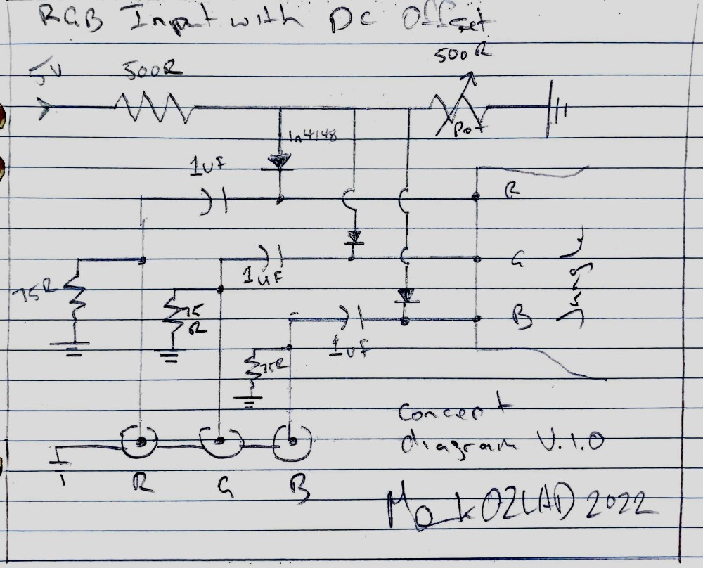
I figured out the problem. This TV needs a DC clamped circuit. I built a simple OP amp clamper circuit and I got RGB properly working. I'll post more later.MarkOZLAD wrote:
This is how I think the RGB input with DC offset could work. Interested in feedback.
Not quite sure how to Mux it yet. Still thinking about that.
https://www.maximintegrated.com/en/desi ... /3303.html
https://www.youtube.com/watch?v=xU7nGvADHZM
Last edited by Ryeno on Thu Jun 09, 2022 10:31 pm, edited 3 times in total.
Re: TV RGB mod thread
Hmm, interesting. Can the black levels be fixed satisfactorily by adjusting the RGB cutoffs, sub brightness, or G2? 1.5vpp with no bias seems easier to work with than I'd thought.Ryeno wrote: I tried adding BIAS to the RGB pins and that doesn't work. I did get the RGB setup to almost work properly with the THS7316 amp but the black level is too high now. Attached is an album with pictures showing the issue. I also measured the factory OSD output and I didn't see any bias so I don't think the bias theory is correct. I need to think more.
https://imgur.com/a/DlD1uHJ
Somewhere back in the depths of this thread is a post where somebody fed RGB straight from a Neo MVS board and got a good picture. IIRC that's around 4vpp?
Re: TV RGB mod thread
Can someone see if this sharp tv is rgb moddable?
It's a sharp 36j-s400. The set seems to be uncommon. I couldn't find it on ebay or any other marketplace. Luckily got this one free locally on Facebook.
Service manual: https://elektrotanya.com/sharp_sn71_cha ... nload.html
Thanks for any input.
It's a sharp 36j-s400. The set seems to be uncommon. I couldn't find it on ebay or any other marketplace. Luckily got this one free locally on Facebook.
Service manual: https://elektrotanya.com/sharp_sn71_cha ... nload.html
Thanks for any input.
-
InfamousSabre
- Posts: 12
- Joined: Fri Jul 22, 2016 1:57 pm
Re: TV RGB mod thread
I'm back again with a new set. I found an RCA 25GT240 with a CTC185AA9 chassis at a Goodwill and picked it up after finding the service manual online and seeing that it has OSD on a separate chip.
https://elektrotanya.com/rca_25gt240tx3 ... nload.html
The part I'm stuck on is this is an RF only set. Where on earth do I tap to input sync? It uses a LA7612N chip, and looking at the diagram I assume sync should be wired to Pin 38 (LUMA IN), but I'm seeing a lot in this thread about not applying sync directly to the chip. What other circuitry should I have in between?
-
KPackratt2k
- Posts: 212
- Joined: Sun Apr 04, 2021 11:02 pm
- Location: Seattle, WA, USA
Re: TV RGB mod thread
One spot you could inject your sync into is the composite video line from the tuner to the jungle chip. You should find out where the composite baseband video from the tuner is being sent to the jungle chip, isolate its circuit, and attempt to inject a composite video signal somewhere in the line until you find the perfect spot. This will typically require trial and error work depending on how complicated the tuner circuitry is on your set. If the tuner is sending the video to the Luma input of the jungle chip, isolate the circuit and inject your sync there, see if that works.InfamousSabre wrote:I'm back again with a new set. I found an RCA 25GT240 with a CTC185AA9 chassis at a Goodwill and picked it up after finding the service manual online and seeing that it has OSD on a separate chip.
https://elektrotanya.com/rca_25gt240tx3 ... nload.html
The part I'm stuck on is this is an RF only set. Where on earth do I tap to input sync? It uses a LA7612N chip, and looking at the diagram I assume sync should be wired to Pin 38 (LUMA IN), but I'm seeing a lot in this thread about not applying sync directly to the chip. What other circuitry should I have in between?
Another option could be enabling external composite video input. If you have an EEPROM programmer, try to find EEPROM dumps from sets that have a similar chassis and AV inputs, then flash the firmware onto the EEPROM chip. Make sure to properly backup the original firmware in case the ones you may find don't work. Alternatively, you could locate a switching pin for an external video input on the microcontroller and apply a voltage to it until the screen turns blue/black. If either of these work, locate an External Composite Video Input pin on the jungle chip and inject 75 ohm terminated Composite video/sync through a 0.1uF capacitor. If you can find a schematic for a similar set with an AV input, your best option would be to copy its circuitry and implement it on your set.
I haven't downloaded the schematic, so I don't really know the specifics off-hand, but either of these methods could be used to inject a sync signal on an RF-only set.
Before proceeding with the mod, make sure the set isn't a hot chassis. A transformer between the tuner and the coaxial input jack is an easy way to spot one. If it is a hot chassis, you will need an isolation transformer to prevent your console from shorting out the set.
-
InfamousSabre
- Posts: 12
- Joined: Fri Jul 22, 2016 1:57 pm
Re: TV RGB mod thread
Unfortunately the tuner isn't part of the service manual and from the lines I can see going to and from the tuner, I can't really make out what should be composite.KPackratt2k wrote:One spot you could inject your sync into is the composite video line from the tuner to the jungle chip. You should find out where the composite baseband video from the tuner is being sent to the jungle chip, isolate its circuit, and attempt to inject a composite video signal somewhere in the line until you find the perfect spot. This will typically require trial and error work depending on how complicated the tuner circuitry is on your set. If the tuner is sending the video to the Luma input of the jungle chip, isolate the circuit and inject your sync there, see if that works.InfamousSabre wrote:I'm back again with a new set. I found an RCA 25GT240 with a CTC185AA9 chassis at a Goodwill and picked it up after finding the service manual online and seeing that it has OSD on a separate chip.
https://elektrotanya.com/rca_25gt240tx3 ... nload.html
The part I'm stuck on is this is an RF only set. Where on earth do I tap to input sync? It uses a LA7612N chip, and looking at the diagram I assume sync should be wired to Pin 38 (LUMA IN), but I'm seeing a lot in this thread about not applying sync directly to the chip. What other circuitry should I have in between?
Another option could be enabling external composite video input. If you have an EEPROM programmer, try to find EEPROM dumps from sets that have a similar chassis and AV inputs, then flash the firmware onto the EEPROM chip. Make sure to properly backup the original firmware in case the ones you may find don't work. Alternatively, you could locate a switching pin for an external video input on the microcontroller and apply a voltage to it until the screen turns blue/black. If either of these work, locate an External Composite Video Input pin on the jungle chip and inject 75 ohm terminated Composite video/sync through a 0.1uF capacitor. If you can find a schematic for a similar set with an AV input, your best option would be to copy its circuitry and implement it on your set.
I haven't downloaded the schematic, so I don't really know the specifics off-hand, but either of these methods could be used to inject a sync signal on an RF-only set.
Before proceeding with the mod, make sure the set isn't a hot chassis. A transformer between the tuner and the coaxial input jack is an easy way to spot one. If it is a hot chassis, you will need an isolation transformer to prevent your console from shorting out the set.
None of the pins on the LA7612N are labelled composite either, unless I'm missing something. Here's the diagram of that chip.

Also, I thought the RF tuner looked weird. Is this a transformer? Doesn't look like it to me, but this is the first time I've seen a tuner not sticking directly out of the shell. Just a bunch of caps and a couple resistors in there. Nothing on the back side except traces. The set was manufactured in 2001, I'd certainly hope they weren't still making hot chassis sets at that time.

I probed around the board with my multimeter a bit and it looks like this is a hot chassis. The ground the RGB signals are connected to are connected directly to one of the poles on the power plug. Would there be any way to isolate the RGB lines/jacks themselves? After all, the RF jack in a hot chassis set is isolated.
If it had been a free TV, I'd just toss it. However, it cost me money and is in great condition so I'd like to make use of it. A similar chassis I can swap in and keep the tube maybe?
-
KPackratt2k
- Posts: 212
- Joined: Sun Apr 04, 2021 11:02 pm
- Location: Seattle, WA, USA
Re: TV RGB mod thread
You can try using optocouplers to isolate your inputs, though it will require some trial and error work. One other user has tried this before with unknown results, but unfortunately the images he posted are dead.InfamousSabre wrote:I probed around the board with my multimeter a bit and it looks like this is a hot chassis. The ground the RGB signals are connected to are connected directly to one of the poles on the power plug. Would there be any way to isolate the RGB lines/jacks themselves? After all, the RF jack in a hot chassis set is isolated.
If it had been a free TV, I'd just toss it. However, it cost me money and is in great condition so I'd like to make use of it. A similar chassis I can swap in and keep the tube maybe?
viewtopic.php?f=6&t=67071
You can also get an inline isolation transformer to plug the TV into to isolate its chassis. This is also a requirement for many arcade monitors as they are also hot chassis.
It's also possible to replace the chassis with another one that isn't hot, but you'll have to cross-reference the neckboard pinouts for your chassis with your desired chassis to verify compatibility with your tube. It also might not fit properly in your set's casing, but if this is going to be for an arcade cabinet setup this shouldn't be a problem. Otherwise, expect to make some heavy modifications to the case.
-
InfamousSabre
- Posts: 12
- Joined: Fri Jul 22, 2016 1:57 pm
Re: TV RGB mod thread
Is there a known place to cross reference chassis/tube compatibility, or is it just a bunch of Google-work?KPackratt2k wrote: It's also possible to replace the chassis with another one that isn't hot, but you'll have to cross-reference the neckboard pinouts for your chassis with your desired chassis to verify compatibility with your tube. It also might not fit properly in your set's casing, but if this is going to be for an arcade cabinet setup this shouldn't be a problem. Otherwise, expect to make some heavy modifications to the case.
Re: TV RGB mod thread
Hello frens! Been lurking here to learn for a while now and I just got my hands on a Panasonic WV-CK2020A which I'm looking to mux mod. There are a couple things I'm a little confused about though, was hoping to get a proofread on my schematic. Here's the service manual I found for the set.
https://www.surveillance-video.com/medi ... Manual.pdf
This set's OSD sends blank with 3 resistors on the line. I'm not sure which one to remove/replace with the RGB blank. The OSD blank goes to a 1.8k ohm R to a capacitor going to ground. Then it goes to another 5.6k resistor, and then to 2.7k resistor before entering the jungle.
My assumption was to replace the second resistor(5.6k) with a 5.6k resistor coming from external blank. The jungle accepts blank for RGB between 1.2v and 3.3v. Any help would be greatly appreciated!
Last edited by Minitron on Fri Jun 17, 2022 9:19 pm, edited 1 time in total.
Re: TV RGB mod thread
This isn't correct.Minitron wrote:
Hello frens! Been lurking here to learn for a while now and I just got my hands on a Panasonic WV-CK2020A which I'm looking to mux mod. There are a couple things I'm a little confused about though, was hoping to get a proofread on my schematic. Here's the service manual I found for the set.
https://www.surveillance-video.com/medi ... Manual.pdf
This set's OSD sends blank with 3 resistors on the line. I'm not sure which one to remove/replace with the RGB blank. The OSD blank goes to a 1.8k ohm R to a capacitor going to ground. Then it goes to another 5.6k resistor, and then to 2.7k resistor before entering the jungle.
My assumption was to replace the second resistor(5.6k) with a 5.6k resistor coming from external blank. The jungle accepts blank for RGB between 1.2v and 3.3v. Any help would be greatly appreciated!
RGB
The factory RGB lines are Vin=5V, R1=5600, R2=910.

The standard method is to replace the 910 resistor with a 820+75 ohm resistors. If the resistors are throughhole then lift the leg of the resistor on the ground side and solder the 75 resistor in the hole. If the resistors are surface mount then you must remove them and use the jumper JS652 to add your resistors


Blanking
Fast blanking
Internal TV.................. 0 to 0.8V
External RGB............1.2 to 3.3V
Harf Tone.................... 3.7 to 5V
The blanking injection is the exact same as the RGB injection. But you have 2 resistors in parallel to ground so you must remove R653 and replace R654 with a 680 ohm resistor. You'll add a 75ohm resistor between 680 and ground and connect that to SCART-16.
To test external scart blanking, you can use a 5V from the motherboard with a 180ohm inline resistor going to the injection point (between 75 ohm resistor and R654). This is also a method you would use for an external blanking switch.
Pro-tip: buy 1% resistors.
Re: TV RGB mod thread
Above is my updated schematic.(EDIT: removed schematic to prevent confusion for onlookers. Will post when mod is complete.) Just wanted to post it in case others want to attempt. Just so you guys know, someone on eBay is selling 2 more of these sets as NEW OLD STOCK if you are interested. They are 500 TVL security monitors. This is where i got mine, for $169+free shipping. Just PM me for the link if you cant find it there. I'm going to post my final results on this mod in a week or two when I get the parts in.Ryeno wrote:Fast blanking
Internal TV.................. 0 to 0.8V
External RGB............1.2 to 3.3V
Harf Tone.................... 3.7 to 5V
The blanking injection is the exact same as the RGB injection. But you have 2 resistors in parallel to ground so you must remove R653 and replace R654 with a 680 ohm resistor. You'll add a 75ohm resistor between 680 and ground and connect that to SCART-16.
To test external scart blanking, you can use a 5V from the motherboard with a 180ohm inline resistor going to the injection point (between 75 ohm resistor and R654). This is also a method you would use for an external blanking switch.
Pro-tip: buy 1% resistors.

Thank you so much for this detailed response! Final question, if I may... Your assessment takes into account that there are capacitors here coming from the OSD just after the 5.6k resistors? Just want to be as close to 100% sure as I can be here. Again, thank you so much for your help. You went above and beyond!
Last edited by Minitron on Fri Jun 17, 2022 9:18 pm, edited 1 time in total.
Re: TV RGB mod thread
Nice catch. Those are filter caps. You should remove them on the RGB because they'll form a RC low pass filter with the 820ohm resistors. You should be fine without filter caps but If you want to add the filter caps back into the circuit then get 3 ~3.3pF ceramic caps C0G NP0 and install them parallel with the 75 ohm termination resistors to ground.Minitron wrote:so much for this detailed response! Final question, if I may... Your assessment takes into account that there are capacitors here coming from the OSD just after the 5.6k resistors? Just want to be as close to 100% sure as I can be here. Again, thank you so much for your help. You went above and beyond!
https://www.digikey.com/en/products/det ... 06/5802809
You can keep the filter cap on the blanking line. it shouldn't affect the circuit.