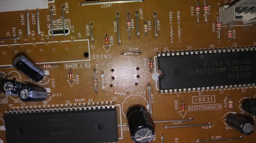
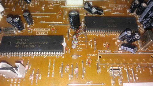
I give up at the Sharp 29ST58 for now as i accidentally break a part of the motherboard (!)while trying to remove it, its really stuck. Surprisingly hes still working , so better found a nice way to remove the board and fix any mess i could be done first. OK my next aim is my trinitron KV-21FE12B Chassi BA-5 , jungle IC1301 CXA2135S and M37273MF as Tuning Control. That one as a easier way to remove what i need to mod, but im still a bit lost here, i see a video from RetroRGB on youtube in which they mod a pretty similar set, so my question is i need to use that creepy 4PDT switch or can i use the same method from 8-bit guy video with single blank/5v switch? also what resistors and /places i need to mod here if using the second option? thanks all!
EDIT: the Manual https://www.electronica-pt.com/esquema/ ... a-5-22506/
RetroRGB video: https://www.youtube.com/watch?v=jbi9HEz-cww&t=446s
TV RGB mod thread
Re: TV RGB mod thread
Last edited by HellRazor on Mon Nov 19, 2018 11:14 pm, edited 1 time in total.
Re: TV RGB mod thread
mgerety wrote:You are a legendMarkOZLAD wrote:
-----------------------------------------------------------------------------------------------------------
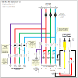
My notes for the BA-5D chassis:
-----------------------------------------------------------------------------------------------------------
RGB Notes
"OSD Mux
Remove R020, R022, R024 SMD resistors that are on the OSD lines. Use 680R or 750R on External RGB lines as well as the normal 75R termination
There are a set of jumper wires on the OSD RGB lines that can be used as our RGB injection point or the solder points from the removed resistors"
Blanking Notes
"5V on Diode leg from OSD Ys. Could possibly put Scart pin 16 to L304."
-----------------------------------------------------------------------------------------------------------
I will definitely be giving this a shot, hopefully this weekend. If I can trace the correct jumper wires I'm happy to report back which they are / how they are marked. Will be picking up the necessary resistors tomorrow.
So, this is likely a pathetically ignorant question, however... : -- if I'm removing the resistors on those OSD lines, should I be bridging the pads with a jumper wire?
Hey you guys, I have a SONY with the same chassis as you two have, I haven't had time to touch mine yet, But i would be interested to view/know your findings and notes along the way, as I will share anything of interest I find as well. I plan to start tinkering with mine on the holiday break, as I'll have a few days off from work.8bitForLife wrote:I have a Kv-27fs200 is it suitable for missing and any idea what candy cabs it might fit

Re: TV RGB mod thread
Hi guys,
this is Christian from Germany. Very nice things you do in this thread, I appreciate the work and documentation
Although in our area it´s not hard to find a tv which is capable of taking RGB inputs (I have a few PVMs, BVMs, B&O) I'm technically interested and would like to mod two professional video monitors I found recently. I mean if I destroy one of them I still have the other.
Could you please help with finding the service manual for the Panasonic BTM1400PSN ?
I cannot finde anything about this model in the internet. It´s a proffesional video monitor, 14" and only has composite input via BNC.
As far as I know it doesnt have a OSD, for all the settings there are buttons on the outside or rotary knobs on the chassis (it´s a monitor, not a tv).
Or do you have any other idea how to start? I already discharged them. For what ICs shall I watch out for ?
Many thanks and Kind Regards
Christian
Re: TV RGB mod thread
I am in the process of properly documenting a proposed mod for the BA-5D utilising the OSD/External RGB Mix. I will create a new thread to put it all in and will add a link here.
The BA-5 chassis method looks like it will be near identical except that the names of all the components appear to have changed in the BA-5D, perhaps to protect the innocent. I'll look to alter for the BA-5 at a later date.
[EDIT] I see the BA-5 Chassis is quite different in manufacture but has almost the exact same OSD circuit.
New thread is here. viewtopic.php?f=6&t=63622&p=1342460#p1342460
___________________________________________________
MarkOZLAD
OSD/External RGB Mux Diagram
OSD/External RGB Mux Resistor Value Table 0.7Vp-p : 0.5Vp-p
"Imagine toggle switch OSD modding a TV in 2019" - maxtherabbit
MarkOZLAD
OSD/External RGB Mux Diagram
OSD/External RGB Mux Resistor Value Table 0.7Vp-p : 0.5Vp-p
"Imagine toggle switch OSD modding a TV in 2019" - maxtherabbit
Re: TV RGB mod thread
Whilst I'm documenting Sony mods, here are the design diagrams I made for John M on the CRT Collective to mod his Sony KV-27S42 TV with BA-4D chassis using the OSD Mux method. He implemented it with great success.
This was done when I was still using diodes.
The basic process is:
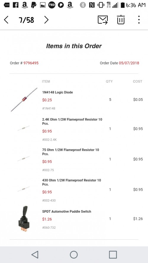
- remove the existing inline throughole resistors R025, R026 and R027
- replace each of them with a 2K4R and a 1n4148 diode
- remove surface mount resistors R086, R087 and R088
- On the external RGB lines use 75R terminations to ground and then 430R inline
- Connect the external RGB lines to the leg of the diodes closest to the jungle
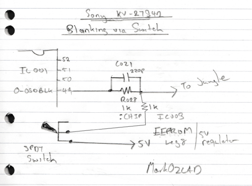
- Connect 5V to switch the switch to 1KR and solder after the existing R028 inline resistor on the blanking circuit
The theory behind the mod exactly the same as for the BA-5D, just a bit easier to implement because of the throughole resistors R025, R026 and R027.
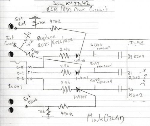
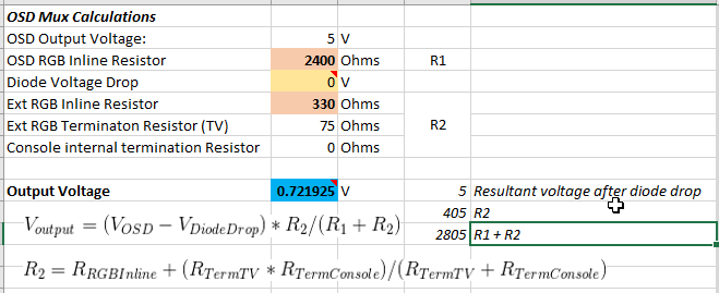
If you wanted to drop the diodes you could use 330R on the External RGB lines.
Or even use 1000R/100R..
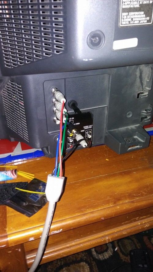
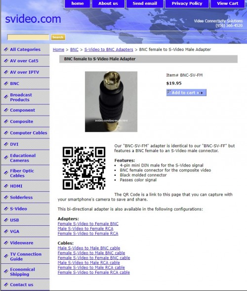
https://www.svideo.com/bnc-sv-fm.html?f ... a2YJAO1zfo


Some other things of note from this mod:
- John was originally using a purchased sync cleaner and couldn't get the TV to sync, he removed this from the setup and it worked
- John purchased an RCA to S-Video adapter and fed sync into S-Video. He said this fixed the image shifting you normally see.
This was done when I was still using diodes.
The basic process is:
- remove the existing inline throughole resistors R025, R026 and R027
- replace each of them with a 2K4R and a 1n4148 diode
- remove surface mount resistors R086, R087 and R088
- On the external RGB lines use 75R terminations to ground and then 430R inline
- Connect the external RGB lines to the leg of the diodes closest to the jungle
- Connect 5V to switch the switch to 1KR and solder after the existing R028 inline resistor on the blanking circuit
The theory behind the mod exactly the same as for the BA-5D, just a bit easier to implement because of the throughole resistors R025, R026 and R027.
If you wanted to drop the diodes you could use 330R on the External RGB lines.
Or even use 1000R/100R..
https://www.svideo.com/bnc-sv-fm.html?f ... a2YJAO1zfo
Some other things of note from this mod:
- John was originally using a purchased sync cleaner and couldn't get the TV to sync, he removed this from the setup and it worked
- John purchased an RCA to S-Video adapter and fed sync into S-Video. He said this fixed the image shifting you normally see.
Last edited by MarkOZLAD on Wed Nov 28, 2018 10:57 pm, edited 8 times in total.
___________________________________________________
MarkOZLAD
OSD/External RGB Mux Diagram
OSD/External RGB Mux Resistor Value Table 0.7Vp-p : 0.5Vp-p
"Imagine toggle switch OSD modding a TV in 2019" - maxtherabbit
MarkOZLAD
OSD/External RGB Mux Diagram
OSD/External RGB Mux Resistor Value Table 0.7Vp-p : 0.5Vp-p
"Imagine toggle switch OSD modding a TV in 2019" - maxtherabbit
-
AntcuFaalb
- Posts: 4
- Joined: Sat Nov 24, 2018 12:24 am
Re: TV RGB mod thread
Can someone help me RGB mod my 50" Pioneer CRT RPTV from '96/97?
I've done some soldering, but I barely know basic electronics so I'd need some hand-holding. I'm more-than-willing to invest the time and effort to learn, FWIW.
The service manual is here: https://drive.google.com/open?id=1FUZP1 ... oXpiXO3-bA
The jungle chip (TA8845BN) datasheet is here: http://pdf.datasheetcatalog.com/datashe ... a/2719.pdf
It has analog RGB input lines in addition to digital(?) OSD RGB input lines. The former shares a sync line with the latter, it seems.
Since this is an RPTV I'd need to retain access to the OSD.
Thanks!
Last edited by AntcuFaalb on Thu Nov 29, 2018 12:44 am, edited 1 time in total.
-
Diopter Doctor

- Posts: 20
- Joined: Sun Sep 16, 2018 2:16 am
Re: TV RGB mod thread
MarkOZLAD wrote:
Really nice work.
For the "large resistor" you talk about on the blanking line, any resistor from 470R up to around 2700R should be fine for that.
If you used a 470R the voltage divider would be 5V * 470 / (470+470) = 2.5V
For 1000R the voltage divider would be 5V * 470 / (470+1000) = 1.5V
For 2000R the voltage divider would be 5V * 470 / (470+2000) = 0.95V
a 2700R would get you 5V * 470 / (470+2700) = 0.74V
Glad you got a great result for your persistence. Persistence is a key skill for this hobby.
I ended up using a 2.5k ohm resistor for the blanking line giving me a little over 0.7V.
I finally got my DPDT switch in the mail and attached it beside the scart input on my rear panel last night.
Switching between RGB and the original TV's inputs works perfectly now.
I had to have the green so it matched the TV remote.
https://www.flickr.com/photos/159678005 ... ed-public/
https://www.flickr.com/photos/159678005 ... ed-public/
Re: TV RGB mod thread
Diopter Doctor wrote: I ended up using a 2.5k ohm resistor for the blanking line giving me a little over 0.7V.
I finally got my DPDT switch in the mail and attached it beside the scart input on my rear panel last night.
Switching between RGB and the original TV's inputs works perfectly now.
I had to have the green so it matched the TV remote.
https://www.flickr.com/photos/159678005 ... ed-public/
https://www.flickr.com/photos/159678005 ... ed-public/
Looks great. Green button was a fine choice.
___________________________________________________
MarkOZLAD
OSD/External RGB Mux Diagram
OSD/External RGB Mux Resistor Value Table 0.7Vp-p : 0.5Vp-p
"Imagine toggle switch OSD modding a TV in 2019" - maxtherabbit
MarkOZLAD
OSD/External RGB Mux Diagram
OSD/External RGB Mux Resistor Value Table 0.7Vp-p : 0.5Vp-p
"Imagine toggle switch OSD modding a TV in 2019" - maxtherabbit
-
Diopter Doctor
- Posts: 20
- Joined: Sun Sep 16, 2018 2:16 am
Re: TV RGB mod thread
First, make sure you look up safety stuff for TVs. Tubes act like huge capacitors and RPTVs have 3 small ones. So, just play it safe.AntcuFaalb wrote:Can someone help me RGB mod my 50" Pioneer CRT RPTV from '96/97?
I've done some soldering, but I barely know basic electronics so I'd need some hand-holding. I'm more-than-willing to invest the time and effort to learn, FWIW.
The service manual is here: https://drive.google.com/open?id=1FUZP1 ... oXpiXO3-bA
The jundle chip (TA8845BN) datasheet is here: http://pdf.datasheetcatalog.com/datashe ... a/2719.pdf
It has analog RGB input lines in addition to digital(?) OSD RGB input lines. The former shares a sync line with the latter, it seems.
Since this is an RPTV I'd need to retain access to the OSD.
Thanks!
Looks like Pin 29-31 is analogue RGB and pin 28 is 1.4V blanking for it (tells the chip to use the incoming RGB signal).
I couldn't follow the schematic to what signal goes there so trace it on the board yourself by using continuity test on your multi-meter.
If it connects to nothing, then solder in jumper wires where ever convenient before the capacitors that are already there. If it is connected to something (like PIP or Teletext), and you don't care about those things then disconnect them and solder in your RGB signal (again, before the factory caps). If you don't want to do either of those, you do have OSD RGB-in to mux into.
What console(s) are you hoping to hook up and what connector (scart, BNC, RCA, etc.) are you wanting to use?
Re: TV RGB mod thread
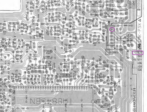
The secondary RGB input of the Jungle, Pins 28/29/30 are all connected to ground via capacitors. Should be able to lift the grounded legs (farthest from the jungle) of capacitors C539, C538 and C540 and inject 75R terminated RGB into them.AntcuFaalb wrote:Can someone help me RGB mod my 50" Pioneer CRT RPTV from '96/97?
I've done some soldering, but I barely know basic electronics so I'd need some hand-holding. I'm more-than-willing to invest the time and effort to learn, FWIW.
The service manual is here: https://drive.google.com/open?id=1FUZP1 ... oXpiXO3-bA
The jungle chip (TA8845BN) datasheet is here: http://pdf.datasheetcatalog.com/datashe ... a/2719.pdf
It has analog RGB input lines in addition to digital(?) OSD RGB input lines. The former shares a sync line with the latter, it seems.
Since this is an RPTV I'd need to retain access to the OSD.
Thanks!
Pin 28 is the blanking pin YS IN. It appears to be soldered directly into ground. Could desolder and lift the leg and connect it to 5V via a switch (or scart pin 16). Connect other side of switch to ground.
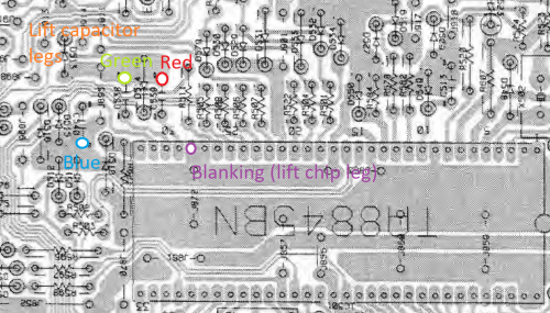
The "Standby 5V" could be used for blanking.
Here is a stitched version of the jungle schematic.
Sync through AV port as per usual...
___________________________________________________
MarkOZLAD
OSD/External RGB Mux Diagram
OSD/External RGB Mux Resistor Value Table 0.7Vp-p : 0.5Vp-p
"Imagine toggle switch OSD modding a TV in 2019" - maxtherabbit
MarkOZLAD
OSD/External RGB Mux Diagram
OSD/External RGB Mux Resistor Value Table 0.7Vp-p : 0.5Vp-p
"Imagine toggle switch OSD modding a TV in 2019" - maxtherabbit
-
arithmaldor

- Posts: 124
- Joined: Wed Jun 07, 2017 8:39 pm
Re: TV RGB mod thread
50" good God, best of luck with that, will be awesome to see the results.
-
AntcuFaalb
- Posts: 4
- Joined: Sat Nov 24, 2018 12:24 am
Re: TV RGB mod thread
So do I just desolder the grounded leg and solder the jumper wire connected to my input BNC to the leg itself?MarkOZLAD wrote:The secondary RGB input of the Jungle, Pins 28/29/30 are all connected to ground via capacitors. Should be able to lift the grounded legs (farthest from the jungle) of capacitors C539, C538 and C540 and inject 75R terminated RGB into them.
Would you use an SPDT switch for this?MarkOZLAD wrote:Pin 28 is the blanking pin YS IN. It appears to be soldered directly into ground. Could desolder and lift the leg and connect it to 5V via a switch (or scart pin 16). Connect other side of switch to ground.
The "Standby 5V" could be used for blanking.
Thank you for all of the help so far!
-
AntcuFaalb
- Posts: 4
- Joined: Sat Nov 24, 2018 12:24 am
Re: TV RGB mod thread
I'm hoping to use a PC @ 640x480. I plan to convert the VGA output from 31 to 15KHz which I assume is what the jungle chip in question needs.Diopter Doctor wrote:What console(s) are you hoping to hook up and what connector (scart, BNC, RCA, etc.) are you wanting to use?
I'm also considering using the RGBS output from my Leitch DPS-575 so that it can act as something like an "RGB mod pre-amp" for whatever SD inputs I plan on providing.
-
AntcuFaalb
- Posts: 4
- Joined: Sat Nov 24, 2018 12:24 am
Re: TV RGB mod thread
I agree! I'm looking forward to it.arithmaldor wrote:50" good God, best of luck with that, will be awesome to see the results.
My Laserdiscs look great on it even at 50" which is surprising.
Re: TV RGB mod thread
MarkOZLAD wrote:The secondary RGB input of the Jungle, Pins 28/29/30 are all connected to ground via capacitors. Should be able to lift the grounded legs (farthest from the jungle) of capacitors C539, C538 and C540 and inject 75R terminated RGB into them.
YesAntcuFaalb wrote:So do I just desolder the grounded leg and solder the jumper wire connected to my input BNC to the leg itself?
MarkOZLAD wrote:Pin 28 is the blanking pin YS IN. It appears to be soldered directly into ground. Could desolder and lift the leg and connect it to 5V via a switch (or scart pin 16). Connect other side of switch to ground.
The "Standby 5V" could be used for blanking.
YesAntcuFaalb wrote:Would you use an SPDT switch for this?
___________________________________________________
MarkOZLAD
OSD/External RGB Mux Diagram
OSD/External RGB Mux Resistor Value Table 0.7Vp-p : 0.5Vp-p
"Imagine toggle switch OSD modding a TV in 2019" - maxtherabbit
MarkOZLAD
OSD/External RGB Mux Diagram
OSD/External RGB Mux Resistor Value Table 0.7Vp-p : 0.5Vp-p
"Imagine toggle switch OSD modding a TV in 2019" - maxtherabbit
Re: TV RGB mod thread
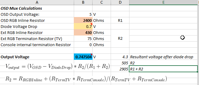
Had a bit of a Eureka moment and realised I could make up a table of resistor values for using the OSD EXT RGB Mux. This should make life a bit easier.
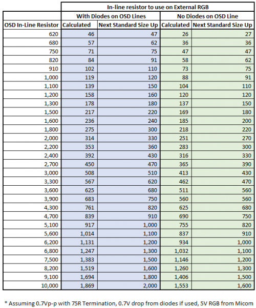
EDIT: Diode based entries were wrong
EDIT: Diode based entries were wrong
Last edited by MarkOZLAD on Tue Dec 04, 2018 5:42 am, edited 1 time in total.
___________________________________________________
MarkOZLAD
OSD/External RGB Mux Diagram
OSD/External RGB Mux Resistor Value Table 0.7Vp-p : 0.5Vp-p
"Imagine toggle switch OSD modding a TV in 2019" - maxtherabbit
MarkOZLAD
OSD/External RGB Mux Diagram
OSD/External RGB Mux Resistor Value Table 0.7Vp-p : 0.5Vp-p
"Imagine toggle switch OSD modding a TV in 2019" - maxtherabbit
Re: TV RGB mod thread
I have a Sharp 36R-S50 that I would like to RGB mod and add a SCART port to. I found the service manual but I’ve never read a schematic before. I have done an RGB mod on my N64 and a few other mods so I can handle soldering I just need help coming up with a plan of where to connect the RGB and Sync signals.
https://elektrotanya.com/cgi-bin/downlo ... sn-92m.pdf
https://elektrotanya.com/cgi-bin/downlo ... sn-92m.pdf
Re: TV RGB mod thread
Successful Mod of Sony KV27FV300 (BA-5D Chassis) using OSD Mix Method.
Details of the mod are in the MarkOZLAD's BA-5D Chassis thread: viewtopic.php?f=6&t=63622&p=1342460#p1342460
This mod is SUPER EASY now that we worked it out.


I'll update with some images showing the OSD overlay later today.
Details of the mod are in the MarkOZLAD's BA-5D Chassis thread: viewtopic.php?f=6&t=63622&p=1342460#p1342460
This mod is SUPER EASY now that we worked it out.
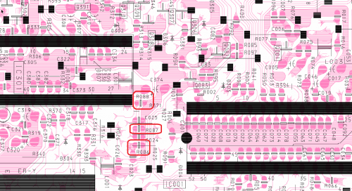
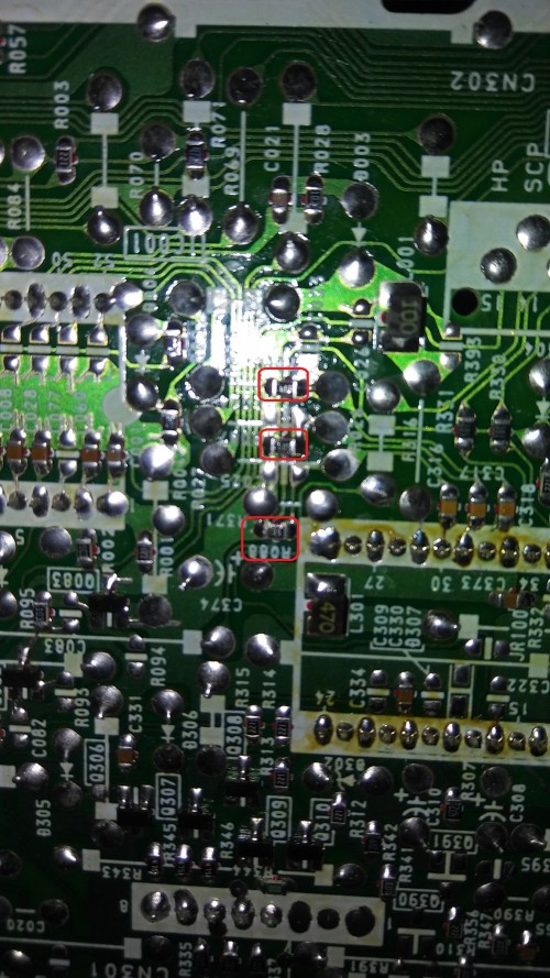
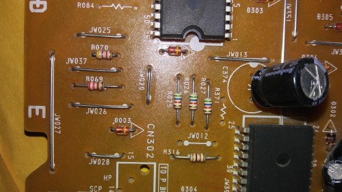
- 1. Remove 3 smd resistors on the bottom side of the A board
- 2. Solder R,G,B, 5V source and Blanking Pin to identified exposed jumper wires on topside of board (see thread above)
- 3. R,G,B wires from source get 75ohm Resistor to Gnd and 750ohm resistor inline.
- 4. Get GND from anywhere (pin 1 on back of svideo port works fine
- 5. For PC mod, add 1k resistor inline on hSync and vSync, twist ends together and pump through composite input.
I'll update with some images showing the OSD overlay later today.
Re: TV RGB mod thread
This is a perfect candidate for the OSD mux method.kynrek wrote:I have a Sharp 36R-S50 that I would like to RGB mod and add a SCART port to. I found the service manual but I’ve never read a schematic before. I have done an RGB mod on my N64 and a few other mods so I can handle soldering I just need help coming up with a plan of where to connect the RGB and Sync signals.
https://elektrotanya.com/cgi-bin/downlo ... sn-92m.pdf
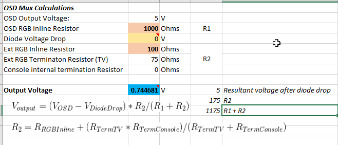
R2024,R2025 and R2026 are your OSD RGB inline resistors, 6800 Ohm
R803, R804 and R805 are the OSD RGB ground resistors. These will need to be removed. Your new inline resistors will be 1100 Ohm (see table above). 75 Ohm terminations of course. As these resistors are surface mount you will probably want to connect your RGB to the legs of R2024,R2025 and R2026 that are closest to the jungle.
R2027 is the inline on blanking, 6800 Ohm, R802 is the ground resistor 3300 ohm. R802 can be removed, then insert a 75 ohm terminated wire from scart pin 16, through a 3300 Ohm resistor onto the leg of R2027 that is closest to the jungle. The jungle requires a minimum of 0.7V to blank which is perfect for using scart pin 16.
The jungle IX3253CE is the same as a TA1268N.
Last edited by MarkOZLAD on Tue Dec 04, 2018 4:11 am, edited 1 time in total.
___________________________________________________
MarkOZLAD
OSD/External RGB Mux Diagram
OSD/External RGB Mux Resistor Value Table 0.7Vp-p : 0.5Vp-p
"Imagine toggle switch OSD modding a TV in 2019" - maxtherabbit
MarkOZLAD
OSD/External RGB Mux Diagram
OSD/External RGB Mux Resistor Value Table 0.7Vp-p : 0.5Vp-p
"Imagine toggle switch OSD modding a TV in 2019" - maxtherabbit
Re: TV RGB mod thread
Awesome, thanks! I’ll crack her open soon and see if I can pinpoint those components. I’ll keep you updated!MarkOZLAD wrote:This is a perfect candidate for the OSD mux method.kynrek wrote:I have a Sharp 36R-S50 that I would like to RGB mod and add a SCART port to. I found the service manual but I’ve never read a schematic before. I have done an RGB mod on my N64 and a few other mods so I can handle soldering I just need help coming up with a plan of where to connect the RGB and Sync signals.
https://elektrotanya.com/cgi-bin/downlo ... sn-92m.pdf
R2024,R2025 and R2026 are your OSD RGB inline resistors, 6800 Ohm
R803, R804 and R805 are the OSD RGB ground resistors. These will need to be removed. Your new inline resistors will be 1100 Ohm (see table above). 75 Ohm terminations of course. As these resistors are surface mount you will probably want to connect your RGB to the legs of R2024,R2025 and R2026 that are closest to the jungle.
R2027 is the inline on blanking, 6800 Ohm, R802 is the ground resistor 3300 ohm. R802 can be removed, then insert a 75 ohm terminated wire from scart pin 16, through a 3300Ohm resistor onto the leg of R2027 that is closest to the jungle. The jungle requires a minimum of 0.7V to blank which is perfect for using scart pin 16.
The jungle IX3253CE is the same as a TA1268N.
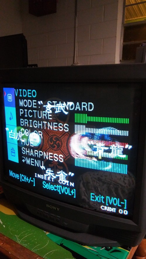
Re: TV RGB mod thread
As promised, here is the OSD on the KV-27FV300.

This time however I have some snowy dots/wavy lines in the picture. Bad ground?
This time however I have some snowy dots/wavy lines in the picture. Bad ground?

Re: TV RGB mod thread
Is your wiring close to the flyback?
Alternatively if you turn down the brightness it should go away.
Alternatively if you turn down the brightness it should go away.
Re: TV RGB mod thread
Nope, turns out it's coming from the PC.
I plugged an LCD monitor into the integrated VGA port (different than the card used for the RGB->TV), and noticed the same pattern on that monitor. When I disconnect the TV completely from the PC, I still get the pattern on the LCD.
I took a video. You can see the pattern in the video, but it's MUCH more pronounced in person.
Is this a bad motherboard?
https://youtu.be/bTT0G2w_Kow
Re: TV RGB mod thread
I am going to summarize to make sure I am understanding what you are recommending:
Remove R803, R804 and R805 and replace with a jumper wire
Change R2024,R2025 and R2026 from 68k to 1.1kMarkOZLAD wrote: R2024,R2025 and R2026 are your OSD RGB inline resistors, 6800 Ohm
R803, R804 and R805 are the OSD RGB ground resistors. These will need to be removed. Your new inline resistors will be 1100 Ohm (see table above).
Remove R803, R804 and R805 and replace with a jumper wire
I don’t know what this 75 ohm termation means. Where do I put the 75ohm resistors? Between the RGB Singnal connected to the legs of R2024 ,R2025 and R2026 closest to the jungle chip and the jungle chip pins themselves and put one end to ground?MarkOZLAD wrote:75 Ohm terminations of course.
Re: TV RGB mod thread
kynrek wrote:I am going to summarize to make sure I am understanding what you are recommending:
Change R2024,R2025 and R2026 from 68k to 1.1kMarkOZLAD wrote: R2024,R2025 and R2026 are your OSD RGB inline resistors, 6800 Ohm
R803, R804 and R805 are the OSD RGB ground resistors. These will need to be removed. Your new inline resistors will be 1100 Ohm (see table above).
Remove R803, R804 and R805 and replace with a jumper wire
I don’t know what this 75 ohm termation means. Where do I put the 75ohm resistors? Between the RGB Singnal connected to the legs of R2024 ,R2025 and R2026 closest to the jungle chip and the jungle chip pins themselves and put one end to ground?MarkOZLAD wrote:75 Ohm terminations of course.
The 1.1K will be the inline resistors on your external RGB lines, they will not replace the existng 6.8K. The 6.8K will remain in place. Remove R803, R804 and R805 but do not jumper them.
Please review the OSD External RGB Mux method.
On the OSD Mux diagram, this is how the 75 Ohm termination is shown
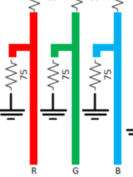
Learn the OSD RGB circuit on your schematic. Good idea to draw up a diagram of the RGB and Blanking (Fast Blanking/YS) circuits including the microcontroller, jungle and all the parts in between. The resistor numbers I've given should help you find it on the schematic. Then look at my instructions and the OSD External RGB Mux diagram.
___________________________________________________
MarkOZLAD
OSD/External RGB Mux Diagram
OSD/External RGB Mux Resistor Value Table 0.7Vp-p : 0.5Vp-p
"Imagine toggle switch OSD modding a TV in 2019" - maxtherabbit
MarkOZLAD
OSD/External RGB Mux Diagram
OSD/External RGB Mux Resistor Value Table 0.7Vp-p : 0.5Vp-p
"Imagine toggle switch OSD modding a TV in 2019" - maxtherabbit
Re: TV RGB mod thread
You should try with another PC power supply, it´s probably very cheaply made.mgerety wrote:Nope, turns out it's coming from the PC.
I plugged an LCD monitor into the integrated VGA port (different than the card used for the RGB->TV), and noticed the same pattern on that monitor. When I disconnect the TV completely from the PC, I still get the pattern on the LCD.
I took a video. You can see the pattern in the video, but it's MUCH more pronounced in person.
Is this a bad motherboard?
https://youtu.be/bTT0G2w_Kow
Re: TV RGB mod thread
New PC power supply on the way from Amazon due tomorrow. It is the power supply for sure. I was able to change and even eliminate the interference by manipulating the cables coming out of the PSU. New modular power supply incoming.

Re: TV RGB mod thread
Its likely a problem with the integrated graphics on the PC, although you can try a new PSU for giggles, but I doubt that will work. What CPU do you have?mgerety wrote:Nope, turns out it's coming from the PC.
I plugged an LCD monitor into the integrated VGA port (different than the card used for the RGB->TV), and noticed the same pattern on that monitor. When I disconnect the TV completely from the PC, I still get the pattern on the LCD.
I took a video. You can see the pattern in the video, but it's MUCH more pronounced in person.
Is this a bad motherboard?
https://youtu.be/bTT0G2w_Kow
-
FinalBaton

- Posts: 4474
- Joined: Sun Mar 08, 2015 10:38 pm
- Location: Québec City
Re: TV RGB mod thread
man, the colours on that Last Blade pic are nuts
all pictures of the modded KV-xxS42 sets I've seen look super good and really enjoyable for gaming. I'le be on the lookout for a cheap one
all pictures of the modded KV-xxS42 sets I've seen look super good and really enjoyable for gaming. I'le be on the lookout for a cheap one
-FM Synth & Black Metal-
Re: TV RGB mod thread
New PSU solved the problem.