A few years ago I got a bunch of SCART cables for my SNES, Genesis and Saturn consoles. At the time, I wasn't really aware of the differences between the different types of sync signals, so I went with the more standard sync on composite video solution.
I've recently learned that a problem I've been noticing (some vertical moving checkerboard pattern) was related to the fact that I was using this sync strategy. Now I want the better quality CSYNC, but I would like to avoid spending lots of money on new cables.
So the question is: can I easily convert the cables to use CSYNC on my own? Is it just a matter of changing the output pin wiring for each console or is it more complicated than that?
I've heard some scalers and TVs and even some consoles have issues with CSYNC, but in my case, at least from what I've read, this shouldn't be a concern, as I have a first model SNES, a model 2 Genesis and a model 1 Saturn, along with a DVDO iScan HD scaler and Scart Commander SCART switcher from Kleene.
Can I convert sync on composite cables to clear sync?
Can I convert sync on composite cables to clear sync?
Last edited by julealgon on Wed Dec 16, 2015 11:48 pm, edited 1 time in total.

Re: Can I convert composite sync cables to clear sync?
composite sync = csync, what you mean is sync on composite (video). Do modify your cables you would have to open the console side, not the SCART side. If it works on your TV depends on the TV, not on which kind of console you use.
Re: Can I convert composite sync cables to clear sync?
Ah ok, I stand corrected. I've updated the OP to reflect that.blizzz wrote:composite sync = csync, what you mean is sync on composite (video).
Yeah, I was assuming I'd have to change the wiring on the console plug end, that's what I meant with "changing the output pin". Do you think it's feasible though? Are there any instructions out there that could help?blizzz wrote: Do modify your cables you would have to open the console side, not the SCART side.
Notice that I said I'm using a DVDO iScan HD scaler and not a direct TV connection. I've heard that this scaler is very robust in regards to sync types, so I should be fine I guess.blizzz wrote: If it works on your TV depends on the TV, not on which kind of console you use.

Re: Can I convert sync on composite cables to clear sync?
SNES: Open the multiout connector, disconnect pin 3, reconnect to pin 9.
Saturn: open up the miniDIN-10 connector, disconnect pin 8, reconnect to pin 1.
Genesis model 2: open up the miniDIN-9 connector, disconnect pin 4, reconnect to pin 5.
Saturn: open up the miniDIN-10 connector, disconnect pin 8, reconnect to pin 1.
Genesis model 2: open up the miniDIN-9 connector, disconnect pin 4, reconnect to pin 5.
Re: Can I convert sync on composite cables to clear sync?
The sync signal found on some NTSC console AV connectors is what is known as a TTL signal. It's meant for communication between digital ICs on the same circuit board. The sync signal used with RGB video signals is called composite video. As the same suggests, it's mixture of video and sync together. It's what is known as a 75 ohm signal.
While the sync information is the same in both signals, You should not directly connect a TTL signal output (composite sync for the game console) to a 75 ohm signal input (composite video pin on SCART). It sometimes works, but it's very unreliable. THE TWO SIGNALS ARE ELECTRICALLY INCOMPATIBLE. People do it anyway, of course. When it doesn't work they blame the game console, their TV set, their SCART switch, their gods. That's why you read so much contradictory info about this online.
It is possible to adapt the TTL signal to the 75 ohm input with passive components. The method is different for each console. It should be thought of an a modification to the sync circuit of the console, not a stand alone circuit element.
The NTSC Super Nintendo TTL sync needs resistor of about 330 ohms installed in series at the console end.
The Sega Master System, Genesis/Mega Drive, and NTSC Saturn TTL sync requires a resistor of about 470 ohms installed in series at the console end and a capacitor of 220uF (positive leg facing console) at either the console or SCART end.
julealgon,
If your cables have moulded plugs on the console end you would have to cut the plug off and attach a new one to make any changes to the wiring.

Re: Can I convert sync on composite cables to clear sync?
Is the LMN1881 chip of any use then ?
I see people using scart adapters with one built-in, claiming it does the job. Er...dunno what they're talking about.
Anyway does feeding a clean sync signal really change anything picture quality-wise ?
I'm not using any broadcast monitors, only standard scart tv's and scalers+lcd, not sure I have a use for clean sync.
Strikers1945guy wrote:"Do we....eat chicken balls?!"
Re: Can I convert sync on composite cables to clear sync?
The problem is from the non-sync parts of the composite video signal. They can couple into the RGB signal through inductive coupling. This problem gets worse, the longer the cable is so if you use passive SCART switchers or similar you might see it. When using SCART TV sets (CRT) and the framemeister scaler I've never seen the distortion in the picture, myself. Though I am able to measure it with an oscilloscope. I wrote more about it here. http://shmups.system11.org/viewtopic.ph ... 1&start=60Xyga wrote: Anyway does feeding a clean sync signal really change anything picture quality-wise ?
I'm not using any broadcast monitors, only standard scart tv's and scalers+lcd, not sure I have a use for clean sync.
It depends.Xyga wrote:Is the LMN1881 chip of any use then ?
I see people using scart adapters with one built-in, claiming it does the job. Er...dunno what they're talking about.
Here a fairly ordinary sync separator circuit based on the LM1881 chip.
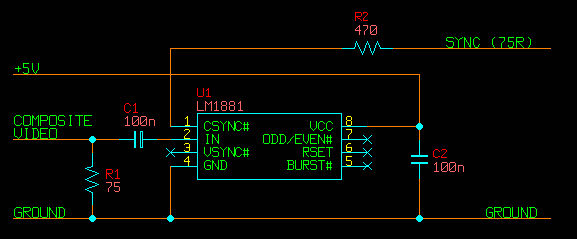
All TV sets contain a circuit just like this, although the sync separator is part of a much larger multi-function video chip. R1 is the video termination resistor. All video signal lines are meant to end with a resistor like this. R2 is required to convert the TTL sync signal output from the LM1881 to 75 ohm sync. C2 is a power supply bypass capacitor. If you placed this circuit into the console end of a SCART cable, it would effectively be the same as a a console wired with TTL sync (as explained in the post above). This could be beneficial because the signal travelling the length of the cable would be sync only, not composite video. If you place this circuit at the SCART end of the cable you would achieve absolutely nothing at all.
Why are some people reporting that a sync separator circuit connected to the SCART end is helpful then? I think what is happening is that these people are building the circuit shown on the first page of the LM1881 datasheet verbatim. It looks like this.
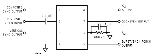
The most important difference is the lack of R1. The composite video signal is unterminated here. Current from each of the four video signals (R,G,B, Composite) are supposed to flow from the console, through their conductors in the cable, through their respective termination resistors (inside the TV or scaler) and back to the console through the ground connection. It is this loop that allows for the coupling to occur. If you break the current current loop of the composite video signal it will stop interfering with the RGB. Isn't this a great idea? Not really, because it solves one problem and creates a few more. Unterminated video will have problems with signal reflection and interference from the RGB signals. The quality of the signal that LM1881 sees on it's input will be quite poor. This explains why it doesn't work properly/at all sometimes.
Re: Can I convert sync on composite cables to clear sync?
Awesome ! Thanks for the calrification viletim. 
Strikers1945guy wrote:"Do we....eat chicken balls?!"
-
bobrocks95

- Posts: 3614
- Joined: Mon Apr 30, 2012 2:27 am
- Location: Kentucky
Re: Can I convert sync on composite cables to clear sync?
So do third-party SCART cable sellers active right now (retro_console_accessories on ebay, retrogamingcables.co.uk, probably some others) put the proper components in the csync cables they sell, or is everyone using them feeding a TTL signal to their equipment? Is it even possible to embed the needed components at the console end of the cable, or does it have to be modified internally? You generally just hear "use csync if your equipment supports it" as a general rule of thumb, I haven't seen anybody address this before.
PS1 Disc-Based Game ID BIOS patch for MemCard Pro and SD2PSX automatic VMC switching.

Re: Can I convert sync on composite cables to clear sync?
You can always do a breakout box if you want to add a sync stripper. If that isn't needed, the larger 8 pin DINs and the SNES multiout are large enough to hold basic components needed like resistors and caps.bobrocks95 wrote:Is it even possible to embed the needed components at the console end of the cable

Re: Can I convert sync on composite cables to clear sync?
It goes inside the Scart head too:
http://www.retrorgb.com/syncstripper.html
http://www.retrorgb.com/syncstripper.html

Re: Can I convert sync on composite cables to clear sync?
Might be a handy to have a new version of this PCB made that uses Tim's application of the LM1881 for 75 ohm output, and 75 ohm termination on the input at the very least! The video input pad is right next to a ground pad, so adding a 75 ohm resistor to the existing design would be trivial.werk91 wrote:It goes inside the Scart head too:
http://www.retrorgb.com/syncstripper.html
Re: Can I convert sync on composite cables to clear sync?
I'll talk to ArcadeTV about that, but to be honest, most people use a sync stripper at the end of the chain, such as the sync strike, or the one built into the gscartsw.
I find the most common scenario people use that board is when using sync-on-luma cables (PS1, N64, etc) on either switches that require csync, or if they're plugging directly into a display that requires csync, like the XM29.
I find the most common scenario people use that board is when using sync-on-luma cables (PS1, N64, etc) on either switches that require csync, or if they're plugging directly into a display that requires csync, like the XM29.

Re: Can I convert sync on composite cables to clear sync?
Wait a minute, you two are not the same person?
Re: Can I convert sync on composite cables to clear sync?
I'm not sure what you mean. I'm Bob, the guy who writes RetroRGB.com. Who else did you think I was?Guspaz wrote:Wait a minute, you two are not the same person?
Re: Can I convert sync on composite cables to clear sync?
I thought RGB32E was also Bob who writes RetroRGB. So imagine my confusion when you started talking to each other 
Re: Can I convert sync on composite cables to clear sync?
If TTL output is desired, then sure it makes sense to not add a 470 ohm resistor on CSYNC out. However, the design might benefit from the input termination, as luma and composite video are both typically 75 ohm loads.retrorgb wrote:I find the most common scenario people use that board is when using sync-on-luma cables (PS1, N64, etc) on either switches that require csync, or if they're plugging directly into a display that requires csync, like the XM29.
Guspaz wrote:I thought RGB32E was also Bob who writes RetroRGB. So imagine my confusion when you started talking to each other
Re: Can I convert sync on composite cables to clear sync?
Wow, there is some very good information on this thread already! You guys are crazy.
So, let me see if I understood this correctly: to convert my cables, I'd have to do what darcagn suggested, changing the source pins on the console end of the connectors, and at the same time add the appropriate resistors and capaciitors as suggested by viletim. Is that correct? If so, I'll see if I can find any electrical technician to perform the soldering for me, as I have absolutely no experience with such things. When I asked the question, I was expecting that it might just be a pin swap, and then I'd be able to do it myself.
Can you guys confirm the exact specs of the resistors and capacitors? Also, is there any other attribute I should look for when buying these components? For instance, is there a difference with "brands" or something like that when shopping for them, or am I good to go with any resistor and capacitor with those specifications?
And about the Genesis cable. You [viletim] mentioned that the larger 8 pin cable (Genesis 1 or Master System) have enough space to house these components, but what can I do in the 9pin DIN though? Is it possible to add a resistor in there or should I go with other solution?
I'll open up one of the cables tomorrow to see if they were molded or not. I bought all of them from one of the more known SCART RGB cable sellers on ebay (don't remember which one now). Hopefuly the console end can be disassembled without destroying it.
Re: Can I convert sync on composite cables to clear sync?
Does the small pcb I linked to work well with the Wii?
I soldered a cable to my syncstrike and my consoles work great but not the Wii.. Is there something special about its Scart cable ground pins? This is a Scart switcher going to the syncstrike and then the output goes directly to the TV with my hacked cable. Some of the ground wires are not soldered but are in full contact as I was trying different combinations.
Photos
Re: Can I convert sync on composite cables to clear sync?
I thought this too!Guspaz wrote:I thought RGB32E was also Bob who writes RetroRGB. So imagine my confusion when you started talking to each other
Re: Can I convert sync on composite cables to clear sync?
They have the components inside. I don't think anybody sells cables that directly connect TTL sync to the video input. They would get a lot of returns!bobrocks95 wrote:So do third-party SCART cable sellers active right now (retro_console_accessories on ebay, retrogamingcables.co.uk, probably some others) put the proper components in the csync cables they sell, or is everyone using them feeding a TTL signal to their equipment? Is it even possible to embed the needed components at the console end of the cable, or does it have to be modified internally? You generally just hear "use csync if your equipment supports it" as a general rule of thumb, I haven't seen anybody address this before.
Use electrolytic capacitors that are small. The voltage rating of 6.3V or greater. Brand doesn't really matter.julealgon wrote: Can you guys confirm the exact specs of the resistors and capacitors? Also, is there any other attribute I should look for when buying these components? For instance, is there a difference with "brands" or something like that when shopping for them, or am I good to go with any resistor and capacitor with those specifications?
Yes, that works. Note that the console end of the connector probably already contains 75 ohm resistors on the R,G,B lines. Use very small resistor (0.125 watt) to make it fit.julealgon wrote:And about the Genesis cable. You [viletim] mentioned that the larger 8 pin cable (Genesis 1 or Master System) have enough space to house these components, but what can I do in the 9pin DIN though? Is it possible to add a resistor in there or should I go with other solution?

Re: Can I convert sync on composite cables to clear sync?
Only to sync-on-luma. Clear sync is BNC-type connercors only, you do can use RGB-to BNC leads and have it connected to SONY BVM/PVM professional studio monitors... but it's complicated way, if your lead is good, stay on sync on composite. I have PAL console and sony official SCART RGB lead, and have no problems with colors checkboard so far.

Re: Can I convert sync on composite cables to clear sync?
To bump a 2 year old post, why is the resistor best placed at the console end, and should that also apply to the ones placed on r/g/b lines too in Megadrive cables?viletim wrote:The sync signal found on some NTSC console AV connectors is what is known as a TTL signal. It's meant for communication between digital ICs on the same circuit board. The sync signal used with RGB video signals is called composite video. As the same suggests, it's mixture of video and sync together. It's what is known as a 75 ohm signal.
While the sync information is the same in both signals, You should not directly connect a TTL signal output (composite sync for the game console) to a 75 ohm signal input (composite video pin on SCART). It sometimes works, but it's very unreliable. THE TWO SIGNALS ARE ELECTRICALLY INCOMPATIBLE. People do it anyway, of course. When it doesn't work they blame the game console, their TV set, their SCART switch, their gods. That's why you read so much contradictory info about this online.
It is possible to adapt the TTL signal to the 75 ohm input with passive components. The method is different for each console. It should be thought of an a modification to the sync circuit of the console, not a stand alone circuit element.
The NTSC Super Nintendo TTL sync needs resistor of about 330 ohms installed in series at the console end.
The Sega Master System, Genesis/Mega Drive, and NTSC Saturn TTL sync requires a resistor of about 470 ohms installed in series at the console end and a capacitor of 220uF (positive leg facing console) at either the console or SCART end.
julealgon,
If your cables have moulded plugs on the console end you would have to cut the plug off and attach a new one to make any changes to the wiring.
System11's random blog, with things - and stuff!
http://blog.system11.org
http://blog.system11.org
Re: Can I convert sync on composite cables to clear sync?
It's due to the parasitic capacitance of the RGB cable. The conductors run next to each other in a cable for a metre or two and form a small capacitance between each other. This is why signals seem to 'talk' to each other inside RGB cables. The capacitance increases with the length of the cable.system11 wrote:To bump a 2 year old post, why is the resistor best placed at the console end, and should that also apply to the ones placed on r/g/b lines too in Megadrive cables?
A TTL sync signal has a large amplitude (3-5 Vpp) and the series resistor attenuates it to something in the area of 0.4 Vpp. If the signal is an order of magnitude smaller when going through the cable it will couple a lot less into the other signals. The victim signal that is most vulnerable to to sync coupling is the audio signal.
For the same reason, the 75 ohm resistors should be placed on the console end inside the Mega Drive RGB cable. There is actually another important reason for this. High speed amplifiers (such as the video encoder) are unstable with capacitive loads. The video encoder requires the 75 ohm resistors placed reasonable close to it to isolate its output from the parasitic capacitance of the cable. Capacitive loads tend to make high speed amplifiers oscillate or otherwise become unstable. There's a note about this in page 12 of the CXA1645P datasheet, but it applies to all video encoders and fast video drivers in general.
In short: Put all resistors in the console end. It reduces the buzz in the audio. In the case of the Mega Drive/Master System it will prevent unpredictable graphical artefacts in the video.

Re: Can I convert sync on composite cables to clear sync?
What's the best way to modify a SNES style "multi-AV" plug? Those look awfully tight to me. MegaDrive, at least, is just some sort of standard DIN.
Re: Can I convert sync on composite cables to clear sync?
Related question (?)
I have an arcade board outputting a 5v TTL CSync signal.
I should adapt this to a 75ohm CSync signal for TV use.
Is this what I should do?
Thanks in advance...
I have an arcade board outputting a 5v TTL CSync signal.
I should adapt this to a 75ohm CSync signal for TV use.
Is this what I should do?
Code: Select all
	CSync (TTL) -> -> 0.1uF cap -> 470ohm resistor -> CSync (75ohm)
		           |
		           v
               75ohm
              resistor
		           |
                 v
GndRe: Can I convert sync on composite cables to clear sync?
On the Capacitors : Usually the higher the voltage rating, the larger the capacitor is.
a 6.3v 100uf capacitor will be smaller physically than one with the same uf but higher voltage.
a 6.3v 100uf capacitor will be smaller physically than one with the same uf but higher voltage.
Re: Can I convert sync on composite cables to clear sync?
Sorry to necro this thread but isn't the reason the sync strike is made the way it is, is that being at the Scart end makes it "universal" as you can just go Scart to Scart? But if you're saying it doesn't work very well and you should have it at the console end then that means you have to make an LM1881 circuit cable for each of your consoles and put it on the console side?viletim wrote: Here a fairly ordinary sync separator circuit based on the LM1881 chip.
All TV sets contain a circuit just like this, although the sync separator is part of a much larger multi-function video chip. R1 is the video termination resistor. All video signal lines are meant to end with a resistor like this. R2 is required to convert the TTL sync signal output from the LM1881 to 75 ohm sync. C2 is a power supply bypass capacitor. If you placed this circuit into the console end of a SCART cable, it would effectively be the same as a a console wired with TTL sync (as explained in the post above). This could be beneficial because the signal travelling the length of the cable would be sync only, not composite video. If you place this circuit at the SCART end of the cable you would achieve absolutely nothing at all.
Any other creative solutions to being able to build one sync separator circuit that you can use on multiple devices? As an aside, does creating a breakout box (like the sync strike) even at the console side make the signal a bit worse because you're creating junctions between wires?