Where to buy your RGB cables and what to look for

The place for all discussion on gaming hardware
viletim
Posts: 550
Joined: Mon Aug 07, 2006 6:44 am
Location: Sydney, Australia
Contact:

Re: Where to buy your RGB cables and what to look for

Post by viletim »

retro_gaming_cables wrote:There is a big enough market for a few sellers, so its always good for customers to have a choice of sellers.

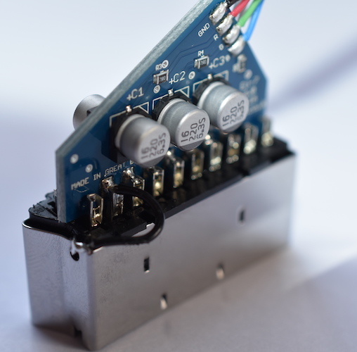
With regards to the dbgrafx booster topic on http://db-electronics.ca we now do our Genesis/Megadrive 2 cables like this (220uF caps on the r,g,b lines plus the 75ohm resistors)
Image
So in theory this cable should now work with the dbgrafx booster, however, as we don't have a dbgrafx booster I am sending a cable off to Bob at RetroRGB.com for testing because he has one.

This is a poor design. You should place the 75 ohm series resistors inside the console end of the cable instead of the SCART end for a Mega Drive (Genesis) 1 or 2 SCART cable. There are three reasons for this.

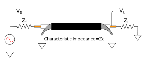
1) It prevents signal reflections. The series resistor is supposed to set the source impedance of the transmission line. The idea is that both source and load (TV) have the same impedance and this reduces cable reflections. If you place the series resistor at the far end of the cable you effectively have a 0 ohm source impedance and a 150 ohm load. This may cause signal reflections (ringing) on sharp edge transitions.

2) It isolates the capacitive load of the cable. Here's a cable data sheet from Belden - 10 core shielded with each conductor being 0.23mm². I'd guess it's reasonably close to what you're using. It states the nominal capacitance between a conductor and shield is 180 pF/metre. That's a 360 pF load for a two metre cable. The reason this is bad is that high frequency (bandwidth), voltage feedback amplifiers generally have a very hard time driving capacitive loads. See the CXA1645 data sheet page 12 and the THS7374 data sheet page 24. Oscillation can can caused by as little as 30 pF of parasitic/stray capacitance. As it is, your cable could certainly cause oscillation in the video encoder RGB driver output under the right conditions.

3) I reduces video signal coupling into the audio (capacitively). See that cable data sheet again. Nominal capacitance from conductor to conductor is ~100 pF/m. As long as there is audio and video sharing the same cable there will be some capacitive coupling between the two. You can have the audio share the length of the cable with the video signals before the resistor or the signal after the resistor. The resistor decreases the amplitude of the video signal by half. Put simply, do you think it is better for the audio signal to share a cable with a big video signal or a little one?

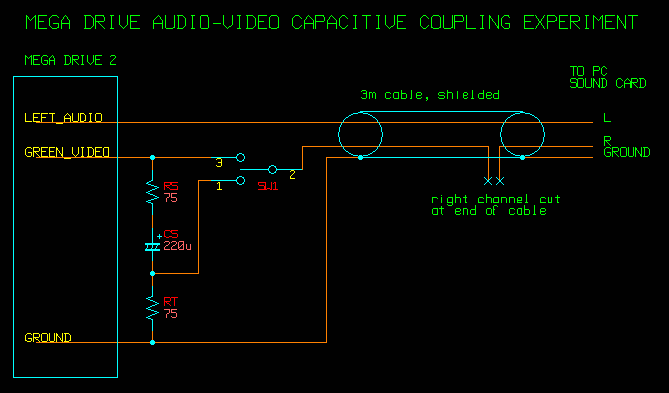
I just tried an experiment to demonstrate this effect. I connected a 3m long, two conductor, shielded cable to the left audio and green video signals. At the console end I'm going to place both the series resistor, coupling capacitor and the termination resistor. The reason I place the termination resistor (which is normally inside the TV) at the console end is I want to measure noise from capacitive coupling only. If I place the termination resistor at the far end I will measure video coupled into the audio by capacitive coupling and + conducted ground coupling. I don't care about conducted ground coupling as it has nothing to do with the placement of the series resistor. The switch SW1 selected what signal will be shared with the audio signal. The video wire is cut right before it enters the PC sound card input.

Image

Results ( .wav format, 30 seconds each, recording my MD2 with Street fighter 2 from power up)
SW1 Position 3 - The audio shares the cable with the video signal before the resistor.
SW1 Position 1 - The audio shares the cable with the video signal after the resistor.
SW1 Centre off - The audio shares the cable with a disconnected wire (control measurement).
retro_gaming_cables
Posts: 23
Joined: Tue Jun 25, 2013 12:19 pm
Location: UK
Contact:

Re: Where to buy your RGB cables and what to look for

Post by retro_gaming_cables »

So what your saying is that the diagram on http://members.optusnet.com.au/eviltim/ ... escart.htm is wrong?

Image

There are no 75 ohm resistors connected to ground for impedance balancing in this diagram to prevent signal reflections. And if they where shouldn't they be at the end of the transmission line, i.e. in the SCART plug? Read this article on impedance matching/balancing. https://en.wikipedia.org/wiki/Impedance_matching

Image

So as an example Zs would be the impedance source from the consoles video encoder and ZL is the impedance balancing/matching resistor at the SCART end of the cable.
viletim
Posts: 550
Joined: Mon Aug 07, 2006 6:44 am
Location: Sydney, Australia
Contact:

Re: Where to buy your RGB cables and what to look for

Post by viletim »

retro_gaming_cables wrote:So what your saying is that the diagram on http://members.optusnet.com.au/eviltim/ ... escart.htm is wrong?
About those diagrams. They are over ten years old and are very much of their time. When I put that page up there was very little info about this on the internet. People were often making direct wire only cables and getting poor results.

The only updates to the page in recent years in when somebody basically demands I fix some error or other. The diagrams are electrically correct, but the page is severely lacking in practical information about making good cables. Mostly because I didn't know much about that at the time.

I have been meaning to fix the page for years now, but I struggle to find the motivation.
retro_gaming_cables wrote: There are no 75 ohm resistors connected to ground for impedance balancing in this diagram to prevent signal reflections. And if they where shouldn't they be at the end of the transmission line, i.e. in the SCART plug? Read this article on impedance matching/balancing. https://en.wikipedia.org/wiki/Impedance_matching

Image

So as an example Zs would be the impedance source from the consoles video encoder and ZL is the impedance balancing/matching resistor at the SCART end of the cable.

Zs is the Sega Mega Drive's video output impedance it is in fact close to zero ohms (a direct connection from the video encoder) when it should be 75 ohms. That's why you add the resistor. It sets the source impedance. By placing the resistor inside the cable you are correcting a problem with the console.

Zl is the termination impedance of the television set. It's already got a 75 ohm resistor in there to ground on each video input. You can measure it with a multimeter. This is not a part of the cable.

Please read my previous post again.
borti4938

Re: Where to buy your RGB cables and what to look for

Post by borti4938 »

retro_gaming_cables wrote:So what your saying is that the diagram on http://members.optusnet.com.au/eviltim/ ... escart.htm is wrong?

Image

There are no 75 ohm resistors connected to ground for impedance balancing in this diagram to prevent signal reflections. And if they where shouldn't they be at the end of the transmission line, i.e. in the SCART plug?
You are selling rgb cable and don't know where the 75ohm load resistors at the SCART-end are... Seriously?
Spoiler
These termination resistors are inside the TV.

(Don't understand me wrong. This could be a question of your customers... "Where are the 'missing' resistors?" So you should be able to answer that.)
By the way. I made a quick experiment on a very cheap LIYY cable (4x0.14mm^2) to show what happens on impedance mismatch. (just a show up for all who are not that technically experienced; I made this experient with my students to appr. determine the length of the cable)
Spoiler
Image
Last edited by borti4938 on Mon Nov 14, 2016 12:47 pm, edited 1 time in total.
retro_gaming_cables
Posts: 23
Joined: Tue Jun 25, 2013 12:19 pm
Location: UK
Contact:

Re: Where to buy your RGB cables and what to look for

Post by retro_gaming_cables »

So its your fault my design in wrong! :D

what your saying is that all the components need to be in the 8 pin DIN plug and not in the SCART plug?
viletim
Posts: 550
Joined: Mon Aug 07, 2006 6:44 am
Location: Sydney, Australia
Contact:

Re: Where to buy your RGB cables and what to look for

Post by viletim »

retro_gaming_cables wrote: what your saying is that all the components need to be in the 8 pin DIN plug and not in the SCART plug?
All series resistors on signal lines go in the console end of the cable. Capacitors can go anywhere.
User avatar
blizzz
Posts: 1150
Joined: Fri Sep 16, 2011 6:19 pm
Location: Germany
Contact:

Re: Where to buy your RGB cables and what to look for

Post by blizzz »

Does the same apply to a PAL SNES cable? All cables I've seen so far had the resistors inside the SCART plug.
viletim
Posts: 550
Joined: Mon Aug 07, 2006 6:44 am
Location: Sydney, Australia
Contact:

Re: Where to buy your RGB cables and what to look for

Post by viletim »

blizzz wrote:Does the same apply to a PAL SNES cable? All cables I've seen so far had the resistors inside the SCART plug.
They are not series resistors, but a double termination. I think it's better to put them in the console end too. Less video signal current flows through ground wire of the cable this way. That means less video signal is coupled into the audio through the ground (conducted ground coupling).
User avatar
rtw
Posts: 1936
Joined: Wed Jan 26, 2005 6:46 pm
Location: Norway
Contact:

Re: Where to buy your RGB cables and what to look for

Post by rtw »

borti4938 wrote:By the way. I made a quick experiment on a very cheap LIYY cable (4x0.14mm^2) to show what happens on impedance mismatch. (just a show up for all who are not that technically experienced; I made this experient with my students to appr. determine the length of the cable)
Spoiler
Image
Would you be so kind to move the picture to imgur ? dropbox is often blocked in a professional environment.
http://world-of-arcades.net
The future of ST-V rests upon our work and your work
borti4938

Re: Where to buy your RGB cables and what to look for

Post by borti4938 »

I don't have a imgur account and also don't want to create one... So - someone else?
viletim wrote:
blizzz wrote:Does the same apply to a PAL SNES cable? All cables I've seen so far had the resistors inside the SCART plug.
They are not series resistors, but a double termination. I think it's better to put them in the console end too. Less video signal current flows through ground wire of the cable this way. That means less video signal is coupled into the audio through the ground (conducted ground coupling).
Personally I would try to add 36ohm resistors in series inside the MultiAV plug instead of 75ohm to ground. This reduces the overall floating current.
The 1chip PAL SNES output is designed with 39ohm output impedance. With the 3chip PAL SNES it is not that easy as there are diodes inside the output lines (cathode directed to output) with 30ohm in series afterwards. But also here 36ohm should be close to be a correct matching.
What do you think about that approach?
User avatar
rtw
Posts: 1936
Joined: Wed Jan 26, 2005 6:46 pm
Location: Norway
Contact:

Re: Where to buy your RGB cables and what to look for

Post by rtw »

borti4938 wrote:I don't have a imgur account and also don't want to create one... So - someone else?
You don't need an account, just go here: http://imgur.com and click on the: New post button
http://world-of-arcades.net
The future of ST-V rests upon our work and your work
viletim
Posts: 550
Joined: Mon Aug 07, 2006 6:44 am
Location: Sydney, Australia
Contact:

Re: Where to buy your RGB cables and what to look for

Post by viletim »

borti4938 wrote:I don't have a imgur account and also don't want to create one... So - someone else?
viletim wrote:
blizzz wrote:Does the same apply to a PAL SNES cable? All cables I've seen so far had the resistors inside the SCART plug.
They are not series resistors, but a double termination. I think it's better to put them in the console end too. Less video signal current flows through ground wire of the cable this way. That means less video signal is coupled into the audio through the ground (conducted ground coupling).
Personally I would try to add 36ohm resistors in series inside the MultiAV plug instead of 75ohm to ground. This reduces the overall floating current.
The 1chip PAL SNES output is designed with 39ohm output impedance. With the 3chip PAL SNES it is not that easy as there are diodes inside the output lines (cathode directed to output) with 30ohm in series afterwards. But also here 36ohm should be close to be a correct matching.
What do you think about that approach?
It's been tried before. There's info buried in the Gamesx forums about it. It doesn't work in practice because Nintendo changed the RGB output circuit over time. The only way to be compatible with all of them it to use the 75 ohm resistor in parallel to ground.
User avatar
rtw
Posts: 1936
Joined: Wed Jan 26, 2005 6:46 pm
Location: Norway
Contact:

Re: Where to buy your RGB cables and what to look for

Post by rtw »

borti4938 wrote:http://imgur.com/a/BAgei
Thank you :D
http://world-of-arcades.net
The future of ST-V rests upon our work and your work
antrasporus
Posts: 1
Joined: Tue Dec 27, 2016 9:11 pm

Re: Where to buy your RGB cables and what to look for

Post by antrasporus »

can someone PM me the contact to thefoo83? I would like to buy a cable from him.
I also wrote him a PM.
If I buy some cables I will review them here.
Thanks.

Edit: I wrote him now a pm and not before, had to wait for authentification, did not know this before.
Post Reply