Well, the simple act of locating the esp about 1" away from the gbs - off to one side, and as far as my current wiring reaches - fixed it. Working flawlessly, no disruption in connectivity/control. And the image is looking fantastic, to boot!Nuck-TH wrote:ESP board antenna should be away from any metal plane like ground plane on bottom of GBS.NoAffinity wrote:Esp is stuck to the bottom of the gbs with some 3m velcro adhesive pads, just like it always has been.
GBS 8200/8220 CFW Project
-
NoAffinity

- Posts: 1081
- Joined: Mon May 07, 2018 5:27 pm
- Location: Escondido, CA, USA
Re: GBS 8200/8220 CFW Project
Re: GBS 8200/8220 CFW Project
Lot's of delayed posts :p
themaxx2k:
The project is meant to be as versatile as possible. Working with lots of systems is the point
You probably want to build a female SCART to VGA adapter. You can then plug your SCART cable into the adapter, and the adapter VGA end into the GBS.
Alternatively, you can build a female SCART receptor with 4 signals + ground going to the posts on the GBS. Electrically, the posts and the VGA input are the same.
Gbscontrol works best with 90s era home consoles (SNES, MD, Saturn, PSX, ..) and also very well with early 2000s stuff that uses Component Video (PS2, Wii, XBOX, ..).
Re: GBS 8200/8220 CFW Project
AtariBits:
Nice to see a new project!
You could speed up development a lot by getting an ESP8266 and build gbscontrol for it.
Connecting the setup to a PC, you can then use a terminal and read out all kinds of information from the running GBS.
It should quickly tell you in what ways you need to modify your preset loading routines.
The register map is not straight forward. You get a couple of sections, then some holes, then some more sections.
There are countless things to watch out for as well. It's not a good idea to just dump a preset into the registers and then expect it to work.
For example, you need to specify the analog input you want to use, and you need to select the correct sync processing for it.
It'll be much easier if you have a working gbscontrol setup to check how it should look like.
Re: GBS 8200/8220 CFW Project
i found this project last week and it interested me to be able to try and clean my video up for my Geneve 9640 (outputs 15kHz)that is connected via RGB to the GBS8200 then out to VGA.
I have built the board based with a NodeMcu ESP8266 D1 Mini and followed the Wiki for hardware setup and uploading of the code.
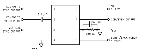
I am using the standard Sync Stripper circuit with the LM1881
I am powering it with a USB cable for testing purposes.
However I get a complete blank screen. I switched the SDA and SCL lines just in case but no difference. Disable the GBSControl and it all works when it uses the internal GBS8200 firmware.
starting
(WiFi): still connecting..
<reset>
Chip ID: 1A 1
G: 3B
R: 3B R: 3C R: 3D R: 3E R: 3F
B: 3B B: 3C B: 3D B: 3E B: 3F B: 40 B: 41
<reset>
<reset>
Scanning inputs for sources ...
(WiFi): STA mode connected; IP: 10.0.0.54
(WiFi): Access 'http://gbscontrol:80' or 'http://gbscontrol.local' (or device IP) in your browser
Activity detected, input: RGB
VSync: present
HSync: present
RGB/HV bypass
ADC offset: R:3F G:3B B:41
RGB/HV bypass on
```````````````<reset>
Any clues?
I have built the board based with a NodeMcu ESP8266 D1 Mini and followed the Wiki for hardware setup and uploading of the code.
I am using the standard Sync Stripper circuit with the LM1881
I am powering it with a USB cable for testing purposes.
However I get a complete blank screen. I switched the SDA and SCL lines just in case but no difference. Disable the GBSControl and it all works when it uses the internal GBS8200 firmware.
starting
(WiFi): still connecting..
<reset>
Chip ID: 1A 1
G: 3B
R: 3B R: 3C R: 3D R: 3E R: 3F
B: 3B B: 3C B: 3D B: 3E B: 3F B: 40 B: 41
<reset>
<reset>
Scanning inputs for sources ...
(WiFi): STA mode connected; IP: 10.0.0.54
(WiFi): Access 'http://gbscontrol:80' or 'http://gbscontrol.local' (or device IP) in your browser
Activity detected, input: RGB
VSync: present
HSync: present
RGB/HV bypass
ADC offset: R:3F G:3B B:41
RGB/HV bypass on
```````````````<reset>
Any clues?

Re: GBS 8200/8220 CFW Project
Hi rama,rama wrote:AtariBits:
Nice to see a new project!
You could speed up development a lot by getting an ESP8266 and build gbscontrol for it.
Connecting the setup to a PC, you can then use a terminal and read out all kinds of information from the running GBS.
It should quickly tell you in what ways you need to modify your preset loading routines.
The register map is not straight forward. You get a couple of sections, then some holes, then some more sections.
There are countless things to watch out for as well. It's not a good idea to just dump a preset into the registers and then expect it to work.
For example, you need to specify the analog input you want to use, and you need to select the correct sync processing for it.
It'll be much easier if you have a working gbscontrol setup to check how it should look like.
Yes that would probably be the right way to approach this, but on my first go around I used an ATTINY681 and the code I got from HERE. And it worked right out of the box giving me this image...
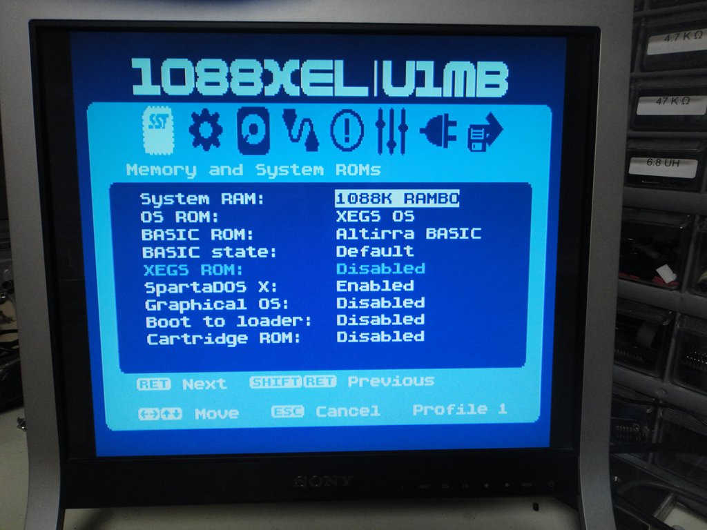
However my projects kind of need to revolve around the use of a PIC chip, due to a cheap programmer board I developed that plugs into the joystick port on an Atari 8-Bit. This combined with an Atari executable flashing file, allows for an extremely easy method of flashing the PIC chips used in my projects using the same computer the projects are destined to upgrade, no PC required. So long story short I thought since the ATTINY681 was working, it should be a relatively easy matter to convert the code over to GCB (Great Cow Basic) and get it on a PIC chip. As it turned out not so easy after all, since my Arduino coding skills are non-existent trying to decipher the code was just not working for me, so I had to try and take an intuitive approach with poor results thus far.
This appears to be the guts of that Arduino code that knows how to deal with the holes and memory offsets required, but try as i might I just don't get what it's really doing in entirety...
Code: Select all
bool writeProgramArray(const uint8_t* programArray)
{
  for(int y = 0; y < 6; y++)
  {
    writeOneByte(0xF0, (uint8_t)y );
    _delay_us(10);

    for(int z = 0; z < 15; z++)
    {
      uint8_t bank[16];
      for(int w = 0; w < 16; w++)
      {
        bank[w] = pgm_read_byte(programArray + (y*256 + z*16 + w));
      }

      writeBytes(z*16, bank, 16);

      _delay_us(10);
    }

  }

  return true;
}Once again I apologize for all the delayed posts, many of which in retrospect were more noise than useful. And I also hope that I haven't derailed this topic too much in the process. My intentions are to eventually get the PIC solution to work, and then to post the code and the gerber files associated with any boards I make running this for anyone to use. Having it in Basic should allow for an easier time if someone else later on wants to create a variant.
BTW, thanks go out to all the people that helped bring the GBS-Control into existence (dooklink, rama, ect.).
Michael from AtariBits
Re: GBS 8200/8220 CFW Project
No worries ;p
I kind of remember that code with the "y*256 + z*16 + w" bits.
First of all, you need to be sure that your preset file matches the algorithm.
This is a big thing with my preset files, since they're stripped down and optimized for my use cases.
They won't work when used with older algorithms.
So anyway, I suggest you take a look at the first post in this thread, and find the Google Drive datasheet archive.
Download the Register Definitions pdf and take a look at the register map.
You can see where the segments are, and how long they are.
Now all you need to do is write some code that fits your preset file values into those segments.
Beware that when you see lots of 0 in the preset file, it often means an overdump, always at the end of a segment.
No meaningful registers exist there, but overdumping simplified the code.
It also helps you spot segment boundaries
Re: GBS 8200/8220 CFW Project
Yes I already found and downloaded the TVia5725 Register and Programming pdfs, and have been using the visual Register Map as a reference. I also went back to the original preset table from that ATTINY681 code, and made it into a GCB table. In that table, I can see the segments and the overdumps in each one to make it an even 256 bytes per segment, and the presets in each segment always start at what would be the 0x00 position. So lots of wasted space with the preset table being a total of 1536 bytes in length. I then referenced the Map and could see how each segment in the table seemed to match up with the number of presets per segment, all except Segment 0 which was kind of odd, having 48 presets, then a 16 byte space (all zeros) and then 16 more presets. Looking at the Register Map, it looks like Segment 0 starts at 0x40 and then ends 32 presets later at 0x5F, then it continues at 0x90 with 16 more presets, ending at 0x9F. I assumed I would have to treat the Segment 0 data in a controlled way, placing two chunks of data starting at specific locations (0x40 and 0x90), but with that first chunk being defined with 48 presets instead of 32, it's rather baffling. Like I mentioned, all the other Segments in the table appear to have the correct number of presets as shown in the Map.rama wrote:No worries ;p
I kind of remember that code with the "y*256 + z*16 + w" bits.
First of all, you need to be sure that your preset file matches the algorithm.
This is a big thing with my preset files, since they're stripped down and optimized for my use cases.
They won't work when used with older algorithms.
So anyway, I suggest you take a look at the first post in this thread, and find the Google Drive datasheet archive.
Download the Register Definitions pdf and take a look at the register map.
You can see where the segments are, and how long they are.
Now all you need to do is write some code that fits your preset file values into those segments.
Beware that when you see lots of 0 in the preset file, it often means an overdump, always at the end of a segment.
No meaningful registers exist there, but overdumping simplified the code.
It also helps you spot segment boundaries
I'll do some more studying of the 5725 data sheets to see if I can figure out what's going on.
Michael from AtariBits
Re: GBS 8200/8220 CFW Project
If it helps any, you can ignore the upper (0x90) segment. The segment just controls the built-in OSD.
So, out of the 0 segment, you really only need registers 0x40 to 0x5f.
0x40 might start with something like 0x7c or 0x3c (SDRAM clock and 648MHz PLL settings).
So, out of the 0 segment, you really only need registers 0x40 to 0x5f.
0x40 might start with something like 0x7c or 0x3c (SDRAM clock and 648MHz PLL settings).
Re: GBS 8200/8220 CFW Project
Hi,
Thanks so much for this project.
I'm using this for a somewhat weird but apparently compatible purpose: to scale the CGA output of a Roland S-330 sampler for use on a 1024x768 VGA LCD. I'm finding it currently works best at 640x480, though I'd love to output the native res of the screen. Already it looks a thousand times better than the GBS8200 by itself, but Is there a way to output 1024x768? The resolution of the sampler output is 340x210, so 1020x630 would be the max integer upscale (3x) I could achieve within 1024x768.
Is this mode currently supported, or is there a way to specify custom resolutions?
Thanks in advance!
Re: GBS 8200/8220 CFW Project
rama - On my 2 GBS- boards I did replace the Sync on Green Capacitor Replacements. I now see that this is not needed. Can I leave the replacement caps in, or is it recommended to put the original values back in?
I am getting a NTSC N64 and planning to get a RGB board so i can get that setup. Annoying having such a poor picture output on this console as standard. The Tom Worthington RGB board looks good as it has a 'deblur' option to get a sharper picture and works on all N64 models.
I am getting a NTSC N64 and planning to get a RGB board so i can get that setup. Annoying having such a poor picture output on this console as standard. The Tom Worthington RGB board looks good as it has a 'deblur' option to get a sharper picture and works on all N64 models.
Re: GBS 8200/8220 CFW Project
gzifcak:
Someone on Github requested the same.
https://github.com/ramapcsx2/gbs-control/issues/79
There isn't much to it to create such a new preset, but then it takes a lot of maintenance effort going forward.
Maybe I can improve my tools enough, so that I can write a small user's guide on how to do this themselves.
Higgy:
Just leave the caps as they are. As long as you don't see lots of sync issues, it is fine.
Sync issues in general should be at their lowest yet. I've managed to get the most signal out of whatever arrives on the pin ;p
Re: GBS 8200/8220 CFW Project
Ooh I'd love to know a little bit about how to do this.rama wrote:gzifcak:
Someone on Github requested the same.
https://github.com/ramapcsx2/gbs-control/issues/79
There isn't much to it to create such a new preset, but then it takes a lot of maintenance effort going forward.
Maybe I can improve my tools enough, so that I can write a small user's guide on how to do this themselves.
Re: GBS 8200/8220 CFW Project
I wrote some tools that take a simple argument and configures a few registers that are appropriate.
For example, if you look up that 1024x768 resolution (https://www.mythtv.org/wiki/Modeline_Database), it uses 806 total lines.
So you can send this command over serial to the ESP8266: "wvt 806"
It will program all the vertical output registers appropriately.
Now that the vertical is set, you can send the command to correct the horizontal parameters to fit these new vertical timings: "."
And that's all to get something that your display recognizes as 1024x768.
But then there's many more things to configure to actually format the source stream to the new target, and I can't give a simple guide for that.
Re: GBS 8200/8220 CFW Project
I have had extremely bad luck finding a GBS8200 that works. i have returned 5 to various vendores. different issues.
just trying to get it to work with the default internal firmware. i have had 2 that the geometry menu selection will not select, 3 that will not detect the rgb signal.
i have one that works fine on both internal and gbscontrol firmware.
I have bought 2 from ebay and 3 from Amazon from different vendors. Does anyone have a good source that they have had good luck?
Re: GBS 8200/8220 CFW Project
Five?
Well, that's certainly odd.
Did you test them all with gbscontrol?
I'm asking because the default firmware doesn't work with a lot of regular consoles, or only works in PAL or NTSC mode, or only interlaced or non-interlaced.
It's very picky.
Oh and the geometry menu is disabled for RGB/HV inputs and I think for YPbPr as well.
Re: GBS 8200/8220 CFW Project
i have made sure they were all setup exactly as the one I currently have working. I even just swapped harnesses from the one that works to the ones that did not. all i get is 'No Signal' even after I power up the console.
I did not see an option within the default firmware to disable/enable the Geometry based on the input. I am selecting the RGBS input.
I am trying to use it on a standard 80's era computer that accepts the 15kHz.
One of the units I had will see the RGB input but the screen goes green sometimes and at others there the screen will be readable and all but looks like it is divided into 4 quadrants.
Re: GBS 8200/8220 CFW Project
Oh yeah, don't expect the original firmware to work, lol 
It will work with sources where it likes the timings (logic / programmatic part of the ofw), AND the physical signals (amplitude, CSync or H/V Sync, etc).
I don't think the firmwares differ between boards, but the sync signal path has minor to significant differences.
That is probably what makes your source work with only some boards.
What the firmware should do is adjust the sync processor to allow it to work around hardware differences, but it's not even trying..
If you put gbscontrol on it, you should get good results. Make sure to use CSync, if available.
Re: GBS 8200/8220 CFW Project
my latest boards (2) came in today with date code of 20091204, one worked and the other just a solid green screen with default firmware. Loaded gbscontrol and hooked it up and the one that worked with default firmware works with gbscontrol but the other nope..
I saw there was a new 5.x version of GBS8200 out, will gbscontrol work with it?
I saw there was a new 5.x version of GBS8200 out, will gbscontrol work with it?
Re: GBS 8200/8220 CFW Project
Please take a few picture of the board that doesn't work, view from top.
I need to see the (and be able to read) the labels around the analog input section (where the 3 potentiometers are) and the area south of the Myson controller (near the pin headers for gbscontrol).
My guess is that the board that isn't working has a resistor missing on the Myson CSync input pin.
I need to see the (and be able to read) the labels around the analog input section (where the 3 potentiometers are) and the area south of the Myson controller (near the pin headers for gbscontrol).
My guess is that the board that isn't working has a resistor missing on the Myson CSync input pin.
Re: GBS 8200/8220 CFW Project
Question about GBSControl. I have loaded it on 2 WeMos D1 Mini's successfully. But I have a couple of others that after I connect to the 'gbscontrol' wifi via my iPhone an get a IP address of 192.168.1.100 assigned to me when I try to go to any of the below it just times out
http://gbscontrol
http://gbscontrol.local
http://gbscontrol:80
http://192.168.4.1
However, if I connect via my windows desktop over wifi it works and I can see the WebUI. Keep in mind I have only coded the unit, it is not hooked up to a GBS8200 as of yet.
Anyone seen this, or know of a fix.
my config i am using to compile is:
Board: LOLIN(WEMOS D1 R2 & Mini)
Upload speed : 115200 (also tried 91200)
CPU Frequency: 80mhz
Flash Size: 4M (1M SPIFFS)
IwIP Variant : V2 Low Memory
Erase Flash : Sketch + WiFi Settings
Re: GBS 8200/8220 CFW Project
What I can say is that every ESP8266 module should (does) behave the same with regards to protocol level TCP/IP.
Maybe the phone remembers the different MAC addresses all using the same (gbscontrol) hostname, and then does something weird?
Maybe the phone remembers the different MAC addresses all using the same (gbscontrol) hostname, and then does something weird?
Re: GBS 8200/8220 CFW Project
Damn IOS update caused the issue. had to forget the network and reboot multiple times and finally got it working.
Re: GBS 8200/8220 CFW Project
iOS13 can't connect to the DVR in my brother's car. Have to use an older device. They're definitely doing something funny that breaks device to device WiFi connections.
Re: GBS 8200/8220 CFW Project
Okay, then it's probably the OS applying some network filters for whatever behaviour gbscontrol does.
"Forgetting" / deleting stored WiFi credentials should fix that, and it would work as long as there aren't multiple devices active at the same time.
If I had to debug, I'd start by giving each device a unique hostname.
"Forgetting" / deleting stored WiFi credentials should fix that, and it would work as long as there aren't multiple devices active at the same time.
If I had to debug, I'd start by giving each device a unique hostname.
Re: GBS 8200/8220 CFW Project
Quick question. From an embedded processor point of view, after the processor pokes in all the new presets via I2C, is there anything that requires activation in order for them to take full effect? Such as a software reset or an enable bit that needs setting.
Reason for the question is that I wrote a routine to confirm the settings of all of the presets which is displayed via an RS232 terminal, and my PIC MCU appears to have poked in all of the same exact values as the ATTiny MCU, but the end result is still a garbled mess on screen, whereas the ATTiny MCU's code is successful, rendering a nice image.
Reason for the question is that I wrote a routine to confirm the settings of all of the presets which is displayed via an RS232 terminal, and my PIC MCU appears to have poked in all of the same exact values as the ATTiny MCU, but the end result is still a garbled mess on screen, whereas the ATTiny MCU's code is successful, rendering a nice image.
Michael from AtariBits
Re: GBS 8200/8220 CFW Project
Yes, absolutely.
I have no idea how simple register dumps ever worked to produce an output.
What you need to have is a method to set a particular register by hand / in code.
You need to write a small function for that.
Load your preset, then write the following:
(s = segment, 0 to 5; r = register in HEX)
s0r46 = 0x00, s0r46 = 0xff (digital soft reset)
s0r47 = 0x00, s0r47 = 0xff (digital soft reset)
next are assuming the source is RGBS and you'll be using SOG to extract sync from the 'S' pin (same as HSync pin on the VGA connector)
s5r02 = 0x51 (RGBS input selected, using a pretty compatible SOG slicer level of 8 )
s5r03 = 0x31
s5r20 = 0x0 (sog mode)
s5r3e = 0x20 (this disables macrovision coast, the programmed positions are wrong anyway and this easily prevents getting a lock)
s5r38 = 0x09, s5r39 = 0x09 (large vsync coast values since i don't know what your source is)
s5r55 = 0x0
s5r56 = 0x05 (sog mode, manual clamp)
s5r57 = 0xc0 (use sog sync and vsync coast)
s5r11 = 0x12, s5r11 = 0x92 (this latches the PLLAD, giving you a pixel clock (hope the charge pump and input is correct for the source!))
These should produce some output, I hope.
If not, you should really reconsider that whole avoiding an extra ESP8266 thing.
The device will disappoint you if it isn't adapting to the source perfectly, and plain register dumps don't do that.
Re: GBS 8200/8220 CFW Project
Thank you rama. You've certainly given me much more than what I gleaned from the programmers manual. Although to be fair, I did see those software resets but it wasn't explicit about when those needed to be invoked.
Yes I am coming in through RGBS and have a clean CSYNC connected to the S input via a 680 ohm resistor. The source is coming from a GTIA to RGB upgrade board on my Atari 8-Bit re-engineered motherboard. The sync is derived from an LM1881 with the source sync coming from the GTIA chip, so the LM1881 really acts more as a buffer to produce a clean and strong signal. If I can duplicate the video results I was seeing with the other MCU I'll be happy, and satisfied. However I do hear you about the ESP8266.
BTW, I have the GBS being run from a highly filtered 12 VDC supply.
I'll report back in when I've had a chance to implement what you've given me. And just so you know, it's very much appreciated. The reason I was silent for so long was that I knew I needed to be able to do a complete read of all the registers in order to see what was really happening. That took me a bit to get right, but once in place allowed me to see some errors in what I was doing with the presets.
Michael from AtariBits
Re: GBS 8200/8220 CFW Project
rama your suggested method worked flawlessly on my 1st attempt 
Here is the mainline code I am currently using (relatively simple, being written in Great Cow Basic)...
Preset Tables are stored inline following the main code (presently set for PAL 288P 1280x1024). Later I will add an NTSC modifier based on a switch setting to go in and change a few of the presets to match up with what's required.
I'll be porting this over to a PIC12F1572 which is an 8-pin DIP, making for a very small I2C PCB add-on board. I'll also post some pics and video when I get this a bit more polished, as well as post the final code, schematics, and gerber files for the board.
Thank you for helping me get to this point
Ohh one last thing... My RGBS source is at 0.75v, so even with the monitor's brightness and contrast cranked up, it still could use a slight amount more brightness. I already turned the pots on the GBS all the way CCW, but I'm thinking that the GBS really wants to see 1v video coming in. Is there a way via the presets to adjust the brightness to better suit a 0.75v signal?
Here is the mainline code I am currently using (relatively simple, being written in Great Cow Basic)...
Code: Select all
 wait 100 ms

  For segment = 0 to 5
   GoSub SetBank (segment)   ;Set Bank Address = Segment

    I2CStart
    I2CSend I2C_ADDRESS
    If segment=0 then
      I2CSend 0x40          ;register start address for Segment 0
    Else
      I2CSend 0x00          ;register start address for Segment 1-5
    End If

    readtable Slen, segment+1, length   ;retrieve segment length

; Send the Presets
    For register = 1 to length
      Select Case segment
        Case 0
        readtable P0, register, data
        Case 1
        readtable P1, register, data
        Case 2
        readtable P2, register, data
        Case 3
        readtable P3, register, data
        Case 4
        readtable P4, register, data
        Case 5
        readtable P5, register, data
      End Select
      I2CSend data
    Next register
    I2CStop
  Next segment

; Activate !!!
  GoSub WriteByte (0, 0x46, 0x00)   ;Soft Reset
  GoSub WriteByte (0, 0x46, 0xFF)
  GoSub WriteByte (0, 0x47, 0x00)   ;Soft Reset
  GoSub WriteByte (0, 0x47, 0xFF)
  GoSub WriteByte (5, 0x02, 0x51)   ;RGBS input, SOG slicer level 8
  GoSub WriteByte (5, 0x03, 0x31)
  GoSub WriteByte (5, 0x20, 0x00)   ;SOG Mode
  GoSub WriteByte (5, 0x3E, 0x20)   ;Macrovision Coast Disable
  GoSub WriteByte (5, 0x38, 0x09)   ;Large Vsync Coast Values
  GoSub WriteByte (5, 0x39, 0x09)
  GoSub WriteByte (5, 0x55, 0x00)
  GoSub WriteByte (5, 0x56, 0x05)   ;SOG Mode, Manual Clamp
  GoSub WriteByte (5, 0x57, 0xC0)   ;Use SOG Sync and Vsync Coast
  GoSub WriteByte (5, 0x11, 0x12)   ;Latching PLLAD for Pixel Clock
  GoSub WriteByte (5, 0x11, 0x92)
  End
Code: Select all
; Define Segment Lengths

Table Slen
32
144
64
128
96
112
End Table

; Preset Tables Start Here

; Misc ---------------------------------------------------------------------------
Table P0
124, 164, 0, 0, 37, 1, 95, 7, 63, 0, 0, 0, 0, 42, 0, 48
0, 0, 0, 0, 0, 0, 0, 0, 0, 0, 0, 0, 0, 0, 0, 0
End Table

; Input Formatter, HD-Bypass, Mode detect ----------------------
Table P1
96, 224, 100, 255, 255, 255, 255, 255, 255, 255, 255, 79, 134, 5, 89, 203
18, 0, 71, 0, 44, 3, 92, 0, 87, 3, 135, 0, 111, 2, 16, 0
56, 0, 146, 3, 155, 6, 159, 6, 4, 0, 0, 0, 0, 0, 0, 0
202, 0, 128, 0, 63, 0, 128, 44, 204, 0, 0, 0, 0, 1, 192, 0
0, 1, 192, 0, 0, 1, 192, 0, 0, 1, 192, 0, 0, 1, 192, 0
0, 1, 192, 0, 0, 0, 0, 0, 0, 0, 0, 0, 0, 0, 0, 0
208, 34, 32, 39, 65, 62, 178, 154, 78, 214, 177, 142, 124, 99, 139, 118
112, 98, 133, 105, 83, 72, 93, 148, 178, 70, 198, 238, 140, 98, 118, 156
0, 0, 53, 0, 0, 12, 202, 0, 0, 0, 0, 0, 0, 0, 0, 0
End Table

; De-Interlace ------------------------------------------------------------
Table P2
255, 3, 204, 0, 0, 0, 5, 5, 7, 0, 76, 4, 204, 152, 255, 73
33, 136, 142, 0, 0, 0, 124, 35, 214, 208, 0, 16, 0, 0, 0, 16
81, 2, 4, 15, 0, 0, 76, 12, 0, 0, 0, 0, 0, 0, 0, 0
0, 0, 52, 0, 136, 71, 3, 11, 4, 100, 11, 4, 143, 0, 0, 0
End Table

; Video Processor, PIP ----------------------------------------------
Table P3
2, 244, 164, 194, 176, 164, 6, 23, 124, 194, 150, 0, 0, 6, 8, 128
226, 164, 15, 16, 172, 128, 152, 194, 35, 2, 0, 0, 0, 0, 0, 0
0, 0, 0, 0, 96, 3, 0, 207, 38, 32, 220, 17, 224, 47, 32, 240
64, 26, 0, 0, 0, 125, 31, 44, 0, 0, 0, 0, 0, 0, 144, 0
2, 3, 0, 0, 248, 31, 248, 31, 248, 30, 208, 32, 248, 10, 142, 30
48, 0, 56, 8, 36, 10, 11, 234, 26, 0, 0, 26, 0, 196, 63, 4
4, 155, 128, 9, 233, 239, 127, 64, 210, 13, 216, 223, 63, 0, 0, 0
0, 8, 0, 180, 5, 0, 0, 0, 0, 0, 0, 0, 0, 0, 0, 0
End Table

; Memory, Capture/Playback, FIFO ----------------------------
Table P4
130, 48, 0, 0, 48, 17, 66, 48, 1, 148, 17, 127, 0, 116, 0, 6
0, 146, 1, 1, 150, 5, 0, 0, 0, 0, 0, 0, 0, 0, 0, 0
0, 43, 3, 31, 255, 255, 207, 255, 255, 31, 0, 164, 30, 0, 128, 0
0, 0, 0, 8, 0, 0, 16, 180, 204, 179, 0, 2, 0, 4, 3, 0
4, 0, 105, 0, 255, 255, 7, 255, 255, 7, 0, 68, 0, 224, 40, 62
192, 0, 0, 0, 104, 1, 192, 180, 204, 90, 204, 76, 0, 0, 0, 0
End Table

; ADC, Sync Proc -----------------------------------------------------
Table P5
216, 0, 87, 241, 0, 0, 63, 63, 63, 127, 127, 127, 0, 0, 0, 0
0, 144, 179, 198, 0, 0, 32, 206, 133, 130, 0, 0, 0, 0, 128, 4
208, 32, 15, 0, 64, 0, 5, 0, 0, 0, 15, 0, 0, 4, 0, 4
0, 47, 0, 40, 3, 21, 0, 4, 4, 15, 10, 0, 0, 0, 192, 3
11, 39, 6, 126, 6, 0, 192, 5, 192, 4, 192, 52, 192, 103, 192, 103
192, 0, 192, 5, 192, 192, 33, 192, 5, 192, 1, 200, 6, 0, 0, 0
0, 0, 0, 15, 0, 0, 0, 0, 0, 0, 0, 0, 0, 0, 0, 0
End Table
Thank you for helping me get to this point
Ohh one last thing... My RGBS source is at 0.75v, so even with the monitor's brightness and contrast cranked up, it still could use a slight amount more brightness. I already turned the pots on the GBS all the way CCW, but I'm thinking that the GBS really wants to see 1v video coming in. Is there a way via the presets to adjust the brightness to better suit a 0.75v signal?
Last edited by AtariBits on Tue Sep 24, 2019 1:17 am, edited 1 time in total.
Michael from AtariBits
Re: GBS 8200/8220 CFW Project
That code looks good. Glad you got it working
The device has programmable ADC gain for all 3 channels, plus a few bits to optimize the SOG input.
Since you're using an LM1881, the SOG stuff just has to be somewhat in range. The current values should do that well.
The ADC gain regs are at s5r09, s5r0a, s5r0b and their values are 0x00 (largest gain) to 0xff (lowest gain).
I think the range is good for 0.5Vpp to 1.0Vpp (there are even some advanced range bits on s5r04 that may push the range to 0.25Vpp to 2.0Vpp!).
All in all, the device is awesome for being produced in 2006.
If it had good software back then, everyone would have had access to great RGB / Component upscaling for ages now.
I wish I had better documents that really explain what's going on internally, with the test bus, level readouts, auto ADC offset, etc.
Instead, I had to reverse engineer and guesstimate it all :p
Oh, one thing I'd like to get working is full access to the MTV230 processor that's already onboard.
It surely can hold something the size of your eventual PIC solution and it could be useful as a main or coprocessor.
It helps that some useful signal pins are already connected to it, such as "debug", HS, VS, or a configurable clock output from the TV5725.
-
8bitForLife
- Posts: 48
- Joined: Thu Dec 08, 2011 1:52 am
- Location: Carson City NV
Re: GBS 8200/8220 CFW Project
I have a normal gbs8200. Was working fine but now I can go to menu but it's not showing me the highlighted menu selection. I can still selection options but I gotta guess or count how many I'm pushing up or down.
Any ideas?
Any ideas?