
Sounds good. I'd be intrested in what you've done. I haven't even though about adding component input yet. I suppose there are two options if you still want the Pi connected as a video input. One would be swaping the Luma input from the Pi over to all RGB with a stripped sync on S. The other would be component input into the RGB port, but sync would be an issue as I think you would need a sync stripper as that input may not be connected to a SOG input, I can't remember.MistyAntelope wrote:so i guess i can't keep lurking for ever...
first off this project is pretty awesome, i bought my gbs 8220 to play my snes on one of the pc monitors on my desk but then i found this project and i don't think i will ever use the snes with out this now...
i've been trying to get component input to work with my pal ps2 without luck so i was wondering if anyone in here has some working settings they would share..
i added bookmarks to the register definition pdf because i got tired of scrolling and i've made some scripts to make the .set files easier to read and turn them back into .set files again that i wouldn't mind sharing if anyone is interested.
GBS 8200/8220 CFW Project
Re: GBS 8200/8220 CFW Project
-
MistyAntelope
- Posts: 4
- Joined: Mon Mar 02, 2015 10:27 am
- Location: Denmark
Re: GBS 8200/8220 CFW Project
as mentioned i have it all on my desk so instead of having an extra keyboard for the pi i just use ssh to control the pi.
i have changed the gbs-control.sh to add a menu for fine adjustments and an option to run the script that switches from menu to the current settings.
so that frees up the Luma input.
i have changed the gbs-control.sh to add a menu for fine adjustments and an option to run the script that switches from menu to the current settings.
so that frees up the Luma input.

Re: GBS 8200/8220 CFW Project
Hi All,
Is anyone experiencing noise on their GBS board? Regardless if it is CFW or default firmware? I am not referring to the snow like noise that is common with 50Hz input. The noise I experience is a vertical wave pattern. There are multiple semi-transparent white S shaped waves from top to bottom about a couple inches apart. They are faint but still distracting. I bought my GBS for $30 on ebay, so it could just be my board with cheap capacitors. But the noise is kinda ugly even though I can see the sharpness the CFW provides in the background. If I could get rid of this noise I would be 100% satisfied. Does anyone know what I am referring to? Or is this just my cheap board issue an I need to get a jammaboards.com version?
Thanks,
Ed
-
MistyAntelope
- Posts: 4
- Joined: Mon Mar 02, 2015 10:27 am
- Location: Denmark
Re: GBS 8200/8220 CFW Project
my GBS board is a cheap ebay one and i don't have that problem...
have you tried it on other monitors? i have two cheap pc monitors that both have weird issues with VGA sources.
have you tried it on other monitors? i have two cheap pc monitors that both have weird issues with VGA sources.

Re: GBS 8200/8220 CFW Project
eta: starting with a gbs set file of choice, then:MistyAntelope wrote:so i guess i can't keep lurking for ever...
first off this project is pretty awesome, i bought my gbs 8220 to play my snes on one of the pc monitors on my desk but then i found this project and i don't think i will ever use the snes with out this now...
i've been trying to get component input to work with my pal ps2 without luck so i was wondering if anyone in here has some working settings they would share..
i added bookmarks to the register definition pdf because i got tired of scrolling and i've made some scripts to make the .set files easier to read and turn them back into .set files again that i wouldn't mind sharing if anyone is interested.
S1_00 IF_MATRIX_BYPS 1
S5_02 ADC_INPUT_SEL 00
S5_03 3:1 101
S5_41-44 sog, from ofw 40,192,59,192 (480i only, maybe, if so you could just dump the values that the ofw uses for pal modes)
eta: yeah just checked my 240p settings are different for S5_41-44
Re: GBS 8200/8220 CFW Project
are there any gbs boards out there for sale yet with custom firmware? I may be interested in one when they become available depending on price.
Re: GBS 8200/8220 CFW Project
I'm extremely busy at the moment. I haven't even started on the on board custom firmware.mvsfan wrote:are there any gbs boards out there for sale yet with custom firmware? I may be interested in one when they become available depending on price.
Re: GBS 8200/8220 CFW Project
Great work. I'm definitely interested in trying this. I have a GBS-8220 and am going to buy a Raspberry Pi. I'd rather buy the new Raspberry Pi 2 (as I might use the pi for other projects in the future). I didn't see composite video out on the Pi 2.
Any idea how much would need to be changed to enable compatibility with the Pi 2?
I'm picturing the following usage:
1) Powering up the GBS-8220 and the Pi 2 together
2) SSH into the Pi 2 to get a shell and run the gbs-control.sh script (or leave it in the bash .profile)
3) Use the menu as usual
From looking at the files on the github repo, there may only be a few minimal tweaks I'd need to make/be aware of. Please correct me if I'm missing anything or am mistaken.
-The "patch.inittab" patch might not be needed since I'd be SSHing in (although keeping it probably wouldn't hurt)
-The "config.txt" changes would probably not be needed (no composite video out on the Pi 2)
-If the keyboard commands don't work over SSH, I'd manually run the commands in gbs.conf
Has anyone tried a Pi B+ or Pi 2 (B) yet?
Alternatively, I've been thinking about implementing a lower cost (<$15) microcontroller-based solution (similar to what was mentioned by a previous poster). I have a few Digispark Pros around. A Digispark Pro might be just enough to provide a subset of functionality of the full Pi solution.
I believe the DSPro has 512 bytes of built in EEPROM and 14.5KB of flash (left after the bootloader). Since the gbs-control.sh script modifies a subset of the register values (approx. 20), my assumption is that I'd only need to store those 20 values (and maybe an extra internally used value or two) into the built in EEPROM. The rest of the register values could be hard coded in program code. From what I can see, there are 1536 entries in a set file. The max value of any non-configurable entry is 255, so my assumption is that I would need 1536 bytes to store hard coded entries (including default values for the 20 configurable entries).
The DSPro has 9 or so GPIO pins (after reserving pins for i2c). That could be enough for a basic UI with a couple buttons and LEDs.
Re: GBS 8200/8220 CFW Project
I believe the B+ and 2 have a TRRS 3.5mm jack for audio and composite video. Like old iPod videos. Otherwise your ideas are correct.
The main issue is I2C. It should work fine provided I2C tools and pysmbus work the same.
The main issue is I2C. It should work fine provided I2C tools and pysmbus work the same.
Re: GBS 8200/8220 CFW Project
So while I'm waiting for my RPi2 to arrive, I thought I'd try creating an Arduino/DigisparkPro version.
My current plan for a first stab is to do the following. If I'm missing something or am wrong, please let me know. I'd prefer not break my GBS-8220 because of something I missed.
1) Hard code the start.txt and RGBHV_640x480@60Hz_RGB_240p60.set values into two global arrays
2) Use the Arduino Wire library to mimick the behavior of rawProg.py (with start.txt) and regProg.py (with RGBHV...240p60.set). Specifically, I plan to mimick the behavior of the loops
and
Is this all that would need to be done?
3) Wire the i2c lines to P5 on the GBS-8220, obtain power and ground from the GBS-8220, and short the P8 jumper
After the DigisparkPro is wired up correctly I plan to power on the solution and see how it goes.
I have a couple of questions:
1) Is 0x17 the i2c address of the Pi or the Tiva?
2) Would an initial delay be required before i2c writing is performed ? (the Pi solution takes time to boot. Should that be mimicked?)
3) With delays of 0.01 seconds, it seems like i2c writing should take at little while (maybe a minute or so?). Should video cables be plugged into the GBS-8220 while the registers are being written? I assume the answer is yes as the cables are plugged in when the on-board microcontroller is in control.
My current plan for a first stab is to do the following. If I'm missing something or am wrong, please let me know. I'd prefer not break my GBS-8220 because of something I missed.
1) Hard code the start.txt and RGBHV_640x480@60Hz_RGB_240p60.set values into two global arrays
2) Use the Arduino Wire library to mimick the behavior of rawProg.py (with start.txt) and regProg.py (with RGBHV...240p60.set). Specifically, I plan to mimick the behavior of the loops
Code: Select all
for z in range(0, (len(start)/2) - 1520):
    Tiva.write8(start[z*2], start[(z*2)+1])
time.sleep(0.01)Code: Select all
for y in range(0, 6):
        Tiva.write8(0xF0, y )
        time.sleep(0.01)
        for z in range(0, 15):
            bank = []
            for w in range(0, 16):
                bank.append(start[y*256 + z*16 + w])

            #print bank
            Tiva.writeList(z*16, bank)
3) Wire the i2c lines to P5 on the GBS-8220, obtain power and ground from the GBS-8220, and short the P8 jumper
After the DigisparkPro is wired up correctly I plan to power on the solution and see how it goes.
I have a couple of questions:
1) Is 0x17 the i2c address of the Pi or the Tiva?
2) Would an initial delay be required before i2c writing is performed ? (the Pi solution takes time to boot. Should that be mimicked?)
3) With delays of 0.01 seconds, it seems like i2c writing should take at little while (maybe a minute or so?). Should video cables be plugged into the GBS-8220 while the registers are being written? I assume the answer is yes as the cables are plugged in when the on-board microcontroller is in control.
Re: GBS 8200/8220 CFW Project
You pretty much covered it all. I don't think there will any problems from signals. The address is 0x17. The delays probably don't need to be there, but it doesn't take a minute.
Re: GBS 8200/8220 CFW Project
A few more (hopefully) quick questions:
1) My logic could be off, but I'm seeing that in the rawProg.py loop
only entries 0 through 613 of start.txt are being utilized. Is there a particular reason for this? I ask because about 3KB (20%) of flash could be freed up if values 614-3654 could be removed.
Also, what is the rationale behind the range calculation?
2) Sorry, I'm still confused about the i2c slave address of the Tiva. So 0x17 is the i2c slave address of the Tiva then? Isn't an odd i2c address a read address? Section 10 of the programming guide lists the i2c slave (write) address of the Tiva as either 0xAE or 0x2E (depending on the state of pin 43).
The interface in the Adafruit I2C library is a little different than the Arduino Wire library. I can probably just create wrapper functions as needed. I'll plan on following section 10 of the programming guide:
1) My logic could be off, but I'm seeing that in the rawProg.py loop
Code: Select all
for z in range(0, (len(start)/2) - 1520):
    Tiva.write8(start[z*2], start[(z*2)+1])
time.sleep(0.01)Also, what is the rationale behind the range calculation?
2) Sorry, I'm still confused about the i2c slave address of the Tiva. So 0x17 is the i2c slave address of the Tiva then? Isn't an odd i2c address a read address? Section 10 of the programming guide lists the i2c slave (write) address of the Tiva as either 0xAE or 0x2E (depending on the state of pin 43).
The interface in the Adafruit I2C library is a little different than the Arduino Wire library. I can probably just create wrapper functions as needed. I'll plan on following section 10 of the programming guide:
10.1 I2C Slave Address Selection
5725 host interface support two slave address AE and 2E, which is selected by pin43 SCLSA.
10.2 I2C writing
Write to One Control Register:
-Start Signal
-Slave Address Byte (R/W Bit = Low)
-Base Address Byte
-Data Byte to Base Address
-Stop Signal
Write to Consecutive Control Registers:
-Start Signal
-Slave Address Byte (R/W Bit = Low)
-Base Address Byte
-Data Byte to Base Address
-Data Byte to (Base Address + 1)
-Data Byte to (Base Address + 2)
-Data Byte to (Base Address + 3)
..................
-Stop Signal
Re: GBS 8200/8220 CFW Project
1. I can't remember exactly as I did that kludge to get things working quickly without developing settings for every register. I think I just decreased the settings used until it stopped working. So you probably can reduce to that size. The indexing is for register addresses and data being two separate bytes.
2. I2C addresses can either be described as 8bit or 7bit. Shift one of the two you mentioned down and you will get the 7bit address.
2. I2C addresses can either be described as 8bit or 7bit. Shift one of the two you mentioned down and you will get the 7bit address.
Re: GBS 8200/8220 CFW Project
So I've implemented the arduino code to write the register values via i2c, but no luck yet. I'm posting this to document the development as well as put stuff out there in case anyone has troubleshooting ideas. After more troubleshooting, I'll post the code to Github.
The i2c interactions between the Digispark Pro and the Tiva don't seem to be working. I'm using the TinyWireM i2c library for the Digispark Pro. The return value of TinyWireM.endTransmission() for every write is 1 (from USI_TWI_Master.h, "USI_TWI_NO_ACK_ON_ADDRESS 0x01 // The slave did not acknowledge the address") instead of the expected value of 0 (write successful).
Since the address is the first byte written after the start sequence, i2c itself may not be working between the devices. On the GBS-8220, P5, VCC is 3.3V. The Digispark Pro is powered by USB (i.e. 5V) in order to output messages to my PC for debugging. I don't think the voltage level difference is an issue though, as i2c devices pull lines low rather than set lines high. I have included 10k pull up resistors to VCC (3.3v). The wiring is as follows:
I
The i2c interactions between the Digispark Pro and the Tiva don't seem to be working. I'm using the TinyWireM i2c library for the Digispark Pro. The return value of TinyWireM.endTransmission() for every write is 1 (from USI_TWI_Master.h, "USI_TWI_NO_ACK_ON_ADDRESS 0x01 // The slave did not acknowledge the address") instead of the expected value of 0 (write successful).
Since the address is the first byte written after the start sequence, i2c itself may not be working between the devices. On the GBS-8220, P5, VCC is 3.3V. The Digispark Pro is powered by USB (i.e. 5V) in order to output messages to my PC for debugging. I don't think the voltage level difference is an issue though, as i2c devices pull lines low rather than set lines high. I have included 10k pull up resistors to VCC (3.3v). The wiring is as follows:
Code: Select all
GBS-8220 P5                                                            Digispark Pro

SCL ----------------------------------------------------------------------- SCL
                          | | R=10k ohm
VCC (3.3V) ------------------
                          | | R=10k ohm
SDA ----------------------------------------------------------------------- SDA

GND ----------------------------------------------------------------------- GND
Re: GBS 8200/8220 CFW Project
It's either wrong address or incorrect wiring I think. The board probably has pull ups on it so you may not need any extra.
Re: GBS 8200/8220 CFW Project
Thanks. Hopefully I'll find time to troubleshoot this week. I'll try to borrow an oscope so I can see what exactly is happening on the i2c lines.
Here's the latest debug build (https://github.com/mybook4/DigisparkSke ... BS_Control). If I'm able to get this to work I'll clean up the code. I utilize the TinyWireM library for i2c communication (on a full size arduino perhaps the Wire library could be used instead?). I utilize the DigiKeyboard library for debugging (makes the Digispark Pro a USB keyboard so debug messages are typed into a text editor on the PC I have the Digispark Pro connected to).
Down the road I could possibly add a basic UI using free GPIO and utilize the Digispark Pro's built-in 512 bytes of EEPROM for persistent storage.
P.S. I'm using the Digispark Pro because it's what I have laying around. They are pretty inexpensive too ($13 US) which is nice (http://digistump.com/products/109).
-
Crafty+Mech

- Posts: 395
- Joined: Sat Jan 19, 2013 1:17 am
Re: GBS 8200/8220 CFW Project
i2c is a digital protocol, you need a logic analyzer if you want to investigate the data packets/timing.mybook4 wrote:Thanks. Hopefully I'll find time to troubleshoot this week. I'll try to borrow an oscope so I can see what exactly is happening on the i2c lines.
Re: GBS 8200/8220 CFW Project
Thanks. Agreed. I wanted to do a quick sanity check first to make sure there is some activity on the lines. It's easier for me to get access to a scope. I might be able to get access to a LA, not sure yet.
Depending on what I see, I might try an i2c address sweep to double check the Tiva address. I've been assuming the address is 0x17 (7-bit).
Depending on what I see, I might try an i2c address sweep to double check the Tiva address. I've been assuming the address is 0x17 (7-bit).
Re: GBS 8200/8220 CFW Project
So I finally got a chance to check things out on a scope. I only had a limited amount of time on it (about 15 minutes), but I was able to see that the Tiva was ACKing only some of the i2c traffic sent (so the address 0x17 7-bit, 0x2e 8-bit was correct as expected). I still need to troubleshoot more. Maybe timing is an issue? I forgot to record waveforms for the on-board microcontroller's i2c traffic for comparison.
I'm thinking about picking up a scope for home. I've been meaning to do this for a long time. Any recommendations? I was checking out the Rigol ds1052e as it is pretty cheap ($330 USD) and people seem to like it. I don't want to spend more tha $400.
I'm thinking about picking up a scope for home. I've been meaning to do this for a long time. Any recommendations? I was checking out the Rigol ds1052e as it is pretty cheap ($330 USD) and people seem to like it. I don't want to spend more tha $400.
Re: GBS 8200/8220 CFW Project
check out DS1054Z, the replacement for DS1052E
Re: GBS 8200/8220 CFW Project
Is it possible to shift an image from an vga source? I feed my GBS from a MIST FPGA, and the input for the c64 cores is accepted in Pal and NTSC, but the PAL image ist widely off centre. I tried the rasbpi setup, but I think I made a mistake, because nothing happens when changing settings...
Re: GBS 8200/8220 CFW Project
So 480p in 480p out? That would be possible bit not with any settings I have at the moment.DrChaos wrote:Is it possible to shift an image from an vga source? I feed my GBS from a MIST FPGA, and the input for the c64 cores is accepted in Pal and NTSC, but the PAL image ist widely off centre. I tried the rasbpi setup, but I think I made a mistake, because nothing happens when changing settings...
I have created a 480p to 240p mode for v0.3. But you could just use the default firmware couldn't you?
Re: GBS 8200/8220 CFW Project
I believe I do. I see it on high contrast edges on the Genesis/MD. But it varies by version of G/MD (I have 3 or 4) and by cable I think. I haven't isolated which account for the most variance explained. That said I don't see any problems on the Saturn. I also would be %100 satisfied with the picture quality if not for the little waves on the G/MD. I've personally settled on a Rev 2 VA 4 which seems to have the least.dwards wrote:Hi All,
Is anyone experiencing noise on their GBS board? Regardless if it is CFW or default firmware? I am not referring to the snow like noise that is common with 50Hz input. The noise I experience is a vertical wave pattern. There are multiple semi-transparent white S shaped waves from top to bottom about a couple inches apart. They are faint but still distracting. I bought my GBS for $30 on ebay, so it could just be my board with cheap capacitors. But the noise is kinda ugly even though I can see the sharpness the CFW provides in the background. If I could get rid of this noise I would be 100% satisfied. Does anyone know what I am referring to? Or is this just my cheap board issue an I need to get a jammaboards.com version?
Thanks,
Ed
This is my current setup mounted:
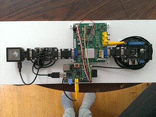
The SLG3k goes into a hammerhead VGA to HDMI converter which is nice and compact. Powered by two 5V 2.5A PSUs. The second PSU is for the sync stripper which gets cleaner signal with its own power.
Re: GBS 8200/8220 CFW Project
MD is a noisy pig, model 2s are somewhat better, cabling can make a big difference, I barely notice it using cat5 but a shielded ps/2 cable was unbearable
at some point i want to try and replace the output cap on the 1.8v ldo to see if thats a problem as mentioned here https://ianstedman.wordpress.com/gbs-82xx-experiments/
at some point i want to try and replace the output cap on the 1.8v ldo to see if thats a problem as mentioned here https://ianstedman.wordpress.com/gbs-82xx-experiments/
Re: GBS 8200/8220 CFW Project
Yes exactly. The MIST has kind of an internal linedoubler, although some of the cores are available in 15khz as well. Through the GBS I get a picture, which is usable in NTSC. But using the original firmware blocks the menue for any picture settings, so no change to center the image in PAL mode. I'll try a cheap vga2hdmi scaler next, it seems that some TV's are more tolerant on HDMI than VGA inputs...dooklink wrote:So 480p in 480p out? That would be possible bit not with any settings I have at the moment.DrChaos wrote:Is it possible to shift an image from an vga source? I feed my GBS from a MIST FPGA, and the input for the c64 cores is accepted in Pal and NTSC, but the PAL image ist widely off centre. I tried the rasbpi setup, but I think I made a mistake, because nothing happens when changing settings...
I have created a 480p to 240p mode for v0.3. But you could just use the default firmware couldn't you?
Re: GBS 8200/8220 CFW Project
Well that's good to know. Also, am I understanding the author correctly that one should use a 680 Ohm resistor between the GBS and Sync Strike?TheRac25 wrote:MD is a noisy pig, model 2s are somewhat better, cabling can make a big difference, I barely notice it using cat5 but a shielded ps/2 cable was unbearable
at some point i want to try and replace the output cap on the 1.8v ldo to see if thats a problem as mentioned here https://ianstedman.wordpress.com/gbs-82xx-experiments/
Re: GBS 8200/8220 CFW Project
ive placed a resistor on the c-sync input and it doesn't appear to harm anything, as to weather or not running without is causing any damage i cant say for certain but thats what the datasheet saysblank964 wrote:Well that's good to know. Also, am I understanding the author correctly that one should use a 680 Ohm resistor between the GBS and Sync Strike?
Re: GBS 8200/8220 CFW Project
Do you think it's possible to install one on the adapter I'm using (see pic above) or would it be best to switch to a cable?TheRac25 wrote:ive placed a resistor on the c-sync input and it doesn't appear to harm anything, as to weather or not running without is causing any damage i cant say for certain but thats what the datasheet saysblank964 wrote:Well that's good to know. Also, am I understanding the author correctly that one should use a 680 Ohm resistor between the GBS and Sync Strike?
Re: GBS 8200/8220 CFW Project
looks like screw terminals into the JST plug would be the only way to go without surgery
Re: GBS 8200/8220 CFW Project
I've stated either here or on the EAB forum that I use a resistor divider to get 3.3v from 5v sync using a 10k and 20k resistor pair. I have this screwed into a sync strike with the wires going into the JST header cable supplied with the GBS. I don't know that a 680 ohm resistor will work with every 5v output, it depends on the output impedance and the impedance of the GBS sync input.