NESRGB board available now
-
MiteWiseacre
- Posts: 22
- Joined: Tue Jan 07, 2020 4:32 pm
Re: NESRGB board available now
Hey guys, I did the nesrgb 2.0 on my front loader yesterday. Installed both the s-video and the multi out for scart that is supplied. SVideo and sound work great! But the scart rgb (on a crt) is only giving me gray scale. I used the Y connection as per the instructions for sync. Should I have used CSync and bridged jumper J8? If I’m getting full colour in svideo does that mean the PPU is properly mounted? Thanks for your help.

Re: NESRGB board available now
I would assume so, but I would also assume that incorrect sync isn't going to effect color, just sync. If I had to guess (just a stab in the dark) there is an issue with your RGB cable wiring.MiteWiseacre wrote:If I’m getting full colour in svideo does that mean the PPU is properly mounted?
Hopefully someone else can chime in to confirm or offer more suggestions.
-
Sefirosu789
- Posts: 83
- Joined: Sun Jul 30, 2017 5:05 pm
- Location: UK
Re: NESRGB board available now
Do you have the right jumper set for your consoles PPU? https://etim.net.au/nesrgb/NESRGB-Pinout.pdfMiteWiseacre wrote:Hey guys, I did the nesrgb 2.0 on my front loader yesterday. Installed both the s-video and the multi out for scart that is supplied. SVideo and sound work great! But the scart rgb (on a crt) is only giving me gray scale. I used the Y connection as per the instructions for sync. Should I have used CSync and bridged jumper J8? If I’m getting full colour in svideo does that mean the PPU is properly mounted? Thanks for your help.
A bit obvious... but make sure your TV can handle the 50hz/60hz! Usually when it can't, the picture will be in black and white. E.G. using a PAL 50hz only TV with an NTSC 60hz console will be black & white.
-
MiteWiseacre
- Posts: 22
- Joined: Tue Jan 07, 2020 4:32 pm
Re: NESRGB board available now
Thanks guys. Yah I closed jumper J8 and J5 as I’m running a ntsc unit. When using the CSync I get no picture at all, blanking is working but getting no RGB I think. I’m pretty sure the B&W was just the video blending through the other sync. SViddo still looks great but still still stuck. I’ll go over all my connections, maybe I messed up the cable?
Re: NESRGB board available now
It's pretty easy to accidentally bridge connections, whether on the NESRGB board or your connections.MiteWiseacre wrote:Thanks guys. Yah I closed jumper J8 and J5 as I’m running a ntsc unit. When using the CSync I get no picture at all, blanking is working but getting no RGB I think. I’m pretty sure the B&W was just the video blending through the other sync. SViddo still looks great but still still stuck. I’ll go over all my connections, maybe I messed up the cable?
Re: NESRGB board available now
That would be my first suspect. Draw yourself a chart of the pins and check continuity for each one. Then check to make sure nothing is shorted (except the ground pins of course).MiteWiseacre wrote:maybe I messed up the cable?
-
Tempest_2084

- Posts: 593
- Joined: Tue Feb 04, 2014 3:05 pm
Re: NESRGB board available now
If this has already been answered on one of the 173 previous pages I apologize. I had a NESRGB board installed in my front loader system years ago (probably the first version as it was early on). I also had a AV multi-port installed at the time. I just discovered however that the expansion audio is not working. Before I got the RGB mod my system had the original expansion audio mod done (the resistor on the expansion port) and later on I got a ENIO board so the system and I know the extra audio worked back then. After doing some research I've discovered that the expansion audio needs to be wired into the NESRGB board for it to work now. I see there are various ways of doing this, but I still have some questions:
1. Do I need to remove the resistor on the expansion port before attempting any of these mods? Will they work with the ENIO board installed (I use it to hook up Famicom peripherals).
2. I'm using a PowerPak cart, what special considerations do I need to look into? One mod mentioned that the person wasn't sure if the resistor values were correct for the PowerPak.
3. Is the switch to turn the expansion audio on/off still needed or is there a way to do this automatically now?
My setup is a US Front Loading NES with an older NESRGB board, palette switch, AV Multi Out port (SCART cable), expansion audio resistor mod, ENIO board, and a Blinking Light Win cartridge port replacement.
-
MiteWiseacre
- Posts: 22
- Joined: Tue Jan 07, 2020 4:32 pm
Re: NESRGB board available now
Got some time today to go over my cable and connections. Looked good, I connected pin21 the frame of the scart to ground because it wasn’t, everything else seems fine. The screen blanks, audio works but no image just pure black. I should be able to detect some DC voltage at the rgb pins on the scart cable while running right?
Edit: checked the voltage at the signal pins on the cable, only getting 1/2v but on other systems I get 3 1/2v. I’m thinking this is he problem? Any advice? Thanks
Edit: checked the voltage at the signal pins on the cable, only getting 1/2v but on other systems I get 3 1/2v. I’m thinking this is he problem? Any advice? Thanks
-
arcadeswede

- Posts: 33
- Joined: Fri Feb 08, 2013 7:14 am
Re: NESRGB board available now
I just added expansion audio to a Twin Famicom with NESRGB and it sounds great!
However, doing so removed the feedback from the mic on the player 2 controller.
I followed Voultars steps at page 115.
Is there any fix for this?
However, doing so removed the feedback from the mic on the player 2 controller.
I followed Voultars steps at page 115.
Is there any fix for this?
-
MiteWiseacre
- Posts: 22
- Joined: Tue Jan 07, 2020 4:32 pm
Re: NESRGB board available now
Is there anyway to boost the signal of the rgbnes? I get only about 0.4v on the RGBS lines, everything else I have is over 1v at least if not 3v. Running on a scart modded crt Toshiba and I don’t think it likes the low signal, just a black screen. Can I mod the scart cable? It’s basically just a through signal (using the cables Tim supplies)
Thanks for any help I can get.
Thanks for any help I can get.
-
nmalinoski
- Posts: 1974
- Joined: Wed Jul 19, 2017 1:52 pm
Re: NESRGB board available now
Voltages for SCART (and thus home consoles) should be 1Vp-p, -0.3V~+0.7V for all of RGB and sync lines. If your other stuff is running +1V or more, your stuff is running unnecessarily hot (or your testing equipment is miscalibrated).MiteWiseacre wrote:Is there anyway to boost the signal of the rgbnes? I get only about 0.4v on the RGBS lines, everything else I have is over 1v at least if not 3v. Running on a scart modded crt Toshiba and I don’t think it likes the low signal, just a black screen. Can I mod the scart cable? It’s basically just a through signal (using the cables Tim supplies)
Thanks for any help I can get.
Generally, I'd recommend making sure you're using the right kind of cable for the way the mod is configured, but the one supplied should work well enough.
-
MiteWiseacre
- Posts: 22
- Joined: Tue Jan 07, 2020 4:32 pm
Re: NESRGB board available now
Thanks for your help. I’ll have to do some research on measuring this stuff properly. It’s weird I have three consoles on scart cables and my SMS is at like 1.3v Genesis higher than that and SNES at over 3v. Sounds like I’m doing something wrong like you say.nmalinoski wrote:Voltages for SCART (and thus home consoles) should be 1Vp-p, -0.3V~+0.7V for all of RGB and sync lines. If your other stuff is running +1V or more, your stuff is running unnecessarily hot (or your testing equipment is miscalibrated).MiteWiseacre wrote:Is there anyway to boost the signal of the rgbnes? I get only about 0.4v on the RGBS lines, everything else I have is over 1v at least if not 3v. Running on a scart modded crt Toshiba and I don’t think it likes the low signal, just a black screen. Can I mod the scart cable? It’s basically just a through signal (using the cables Tim supplies)
Thanks for any help I can get.
Generally, I'd recommend making sure you're using the right kind of cable for the way the mod is configured, but the one supplied should work well enough.
-
Tempest_2084
- Posts: 593
- Joined: Tue Feb 04, 2014 3:05 pm
Re: NESRGB board available now
I can't seem to find any info on adding the expansion audio to the NESRGB board on a front loader. All the info I'm finding is either for the top loader or the Famicom AV. I assume it's possible as I've seen a reference to it being done, but no actual instructions. I find this odd because I always thought this was a pretty common configuration.
-
nmalinoski
- Posts: 1974
- Joined: Wed Jul 19, 2017 1:52 pm
Re: NESRGB board available now
If you're talking the clean composite sync line, voltages higher than video-level is normal; consoles like the Genesis and SNES output [effectively] TTL sync, which is fine if you're using BNC or DE-15 cables into pro AV gear (like Extron RGB switchers), which expect TTL, but it needs to be attenuated in SCART cables to be electrically-compliant if you want to use that over the default composite video for sync.MiteWiseacre wrote:Thanks for your help. I’ll have to do some research on measuring this stuff properly. It’s weird I have three consoles on scart cables and my SMS is at like 1.3v Genesis higher than that and SNES at over 3v. Sounds like I’m doing something wrong like you say.
If you're talking the RGB lines running at that voltages, that's weird.
-
VajSkids Consoles
- Posts: 123
- Joined: Tue Jul 07, 2020 10:22 am
Re: NESRGB board available now
Any tv that does RGB will accept 60hz. It’s not technically ntsc or pal when using RGB but just the refresh rateSefirosu789 wrote:Do you have the right jumper set for your consoles PPU? https://etim.net.au/nesrgb/NESRGB-Pinout.pdfMiteWiseacre wrote:Hey guys, I did the nesrgb 2.0 on my front loader yesterday. Installed both the s-video and the multi out for scart that is supplied. SVideo and sound work great! But the scart rgb (on a crt) is only giving me gray scale. I used the Y connection as per the instructions for sync. Should I have used CSync and bridged jumper J8? If I’m getting full colour in svideo does that mean the PPU is properly mounted? Thanks for your help.
A bit obvious... but make sure your TV can handle the 50hz/60hz! Usually when it can't, the picture will be in black and white. E.G. using a PAL 50hz only TV with an NTSC 60hz console will be black & white.
-
VajSkids Consoles
- Posts: 123
- Joined: Tue Jul 07, 2020 10:22 am
Re: NESRGB board available now
While I’m here can anybody explain the “expansion audio enable” resistor on the OpenTendo where there’s also an unpopulated footprint on the original boards ?? What’s this for, I mean as in... it’s labelled expansion audio enable but it’s never populated/ nor by any mods
-
VajSkids Consoles
- Posts: 123
- Joined: Tue Jul 07, 2020 10:22 am
Re: NESRGB board available now
Dude 1vpp plus .7 ?? That’s 1.7vpp. That brightness will melt your eyes off. The guy stating he gets .4 can’t be right. This product has being selling for years... I think youre reading the DC offsetnmalinoski wrote:Voltages for SCART (and thus home consoles) should be 1Vp-p, -0.3V~+0.7V for all of RGB and sync lines. If your other stuff is running +1V or more, your stuff is running unnecessarily hot (or your testing equipment is miscalibrated).MiteWiseacre wrote:Is there anyway to boost the signal of the rgbnes? I get only about 0.4v on the RGBS lines, everything else I have is over 1v at least if not 3v. Running on a scart modded crt Toshiba and I don’t think it likes the low signal, just a black screen. Can I mod the scart cable? It’s basically just a through signal (using the cables Tim supplies)
Thanks for any help I can get.
Generally, I'd recommend making sure you're using the right kind of cable for the way the mod is configured, but the one supplied should work well enough.
-
VajSkids Consoles
- Posts: 123
- Joined: Tue Jul 07, 2020 10:22 am
Re: NESRGB board available now
I recently installed one of these using an 8pin din panel mount and a cheap $5 C type sega master system/ megadrive one RGB cable with the components in the scart head removed. It’s absolutely crisp and there’s surprisingly no audio interference.MiteWiseacre wrote:Got some time today to go over my cable and connections. Looked good, I connected pin21 the frame of the scart to ground because it wasn’t, everything else seems fine. The screen blanks, audio works but no image just pure black. I should be able to detect some DC voltage at the rgb pins on the scart cable while running right?
Edit: checked the voltage at the signal pins on the cable, only getting 1/2v but on other systems I get 3 1/2v. I’m thinking this is he problem? Any advice? Thanks
I stupidly forgot (the amount of RGB shit I’ve been doing lately too!) to ground my cable and sent photos to Tim knowing he’d help out and support his own product.
Anyway a photo speaks 1000 words. Show us your installation/ photos of screen etc- everything and you’ll find you may get real help.
Apologies for bombing this thread
-
Tempest_2084
- Posts: 593
- Joined: Tue Feb 04, 2014 3:05 pm
Re: NESRGB board available now
I've found a bit of a workaround for my expansion audio issue. It turns out I can still tap the extra audio from the sound port on the side of the NES and mix it into the sound going into my TV with a splitter cable. It works, but the volume is a bit quieter than it should be. I think this has something to do with the resistor value I used in the original mod. Still, until I can get someone to wire it up appropriately it's something.
-
nmalinoski
- Posts: 1974
- Joined: Wed Jul 19, 2017 1:52 pm
Re: NESRGB board available now
I stated the total range (1V peak to peak), followed by the actual range (-0.3V to +0.7V), of what video-level voltages should be. Nowhere did I say 1Vp-p plus 0.7V.VajSkids Consoles wrote:Dude 1vpp plus .7 ?? That’s 1.7vpp. That brightness will melt your eyes off. The guy stating he gets .4 can’t be right. This product has being selling for years... I think youre reading the DC offset
He also still hasn't clarified whether he's referring to the sync line, RGB lines, or both, but the higher voltages he claims for his SMS, Genesis, and SNES (1.3V~3V) seem to me like reasonable voltages for TTL sync for these consoles and not at all like video lines.
He stated 0.4V specifically in regards to the NESRGB (without clarifying which line he's measuring), which is right in the middle of the appropriate voltage range if he's using composite video or luma for sync, but it sounds wrong for clean composite sync, because that's what the -0.3V is supposed to be.
-
MiteWiseacre
- Posts: 22
- Joined: Tue Jan 07, 2020 4:32 pm
Re: NESRGB board available now
I was measuring from the signal lines to ground line using DC on my multimeter.. so these numbers 0.4v are what I got on the RGB signal and the Sync line. Using this wrong method I see higher voltages on the Genesis (well over 1v) etc.. what is the correct way to measure signal strength?nmalinoski wrote:I stated the total range (1V peak to peak), followed by the actual range (-0.3V to +0.7V), of what video-level voltages should be. Nowhere did I say 1Vp-p plus 0.7V.VajSkids Consoles wrote:Dude 1vpp plus .7 ?? That’s 1.7vpp. That brightness will melt your eyes off. The guy stating he gets .4 can’t be right. This product has being selling for years... I think youre reading the DC offset
He also still hasn't clarified whether he's referring to the sync line, RGB lines, or both, but the higher voltages he claims for his SMS, Genesis, and SNES (1.3V~3V) seem to me like reasonable voltages for TTL sync for these consoles and not at all like video lines.
He stated 0.4V specifically in regards to the NESRGB (without clarifying which line he's measuring), which is right in the middle of the appropriate voltage range if he's using composite video or luma for sync, but it sounds wrong for clean composite sync, because that's what the -0.3V is supposed to be.
-
VajSkids Consoles
- Posts: 123
- Joined: Tue Jul 07, 2020 10:22 am
Re: NESRGB board available now
A little pocket digital oscilloscope will work if you don't want to fork out for the real deal but you don't need to measure anything, this is a finished product - I can't even imagine how many NES's have these installed after all these years. If you want help, you need to send photos. Try an IMGUR folder, its free. Also show your television points- make sure you aren't mixing up RGB with the Red/ Green/ blue component video plugs which have sync on green. This is not RGBs. This is YPbPr / component. The board can output this with an additional kit.MiteWiseacre wrote:I was measuring from the signal lines to ground line using DC on my multimeter.. so these numbers 0.4v are what I got on the RGB signal and the Sync line. Using this wrong method I see higher voltages on the Genesis (well over 1v) etc.. what is the correct way to measure signal strength?nmalinoski wrote:I stated the total range (1V peak to peak), followed by the actual range (-0.3V to +0.7V), of what video-level voltages should be. Nowhere did I say 1Vp-p plus 0.7V.VajSkids Consoles wrote:Dude 1vpp plus .7 ?? That’s 1.7vpp. That brightness will melt your eyes off. The guy stating he gets .4 can’t be right. This product has being selling for years... I think youre reading the DC offset
He also still hasn't clarified whether he's referring to the sync line, RGB lines, or both, but the higher voltages he claims for his SMS, Genesis, and SNES (1.3V~3V) seem to me like reasonable voltages for TTL sync for these consoles and not at all like video lines.
He stated 0.4V specifically in regards to the NESRGB (without clarifying which line he's measuring), which is right in the middle of the appropriate voltage range if he's using composite video or luma for sync, but it sounds wrong for clean composite sync, because that's what the -0.3V is supposed to be.
I prefer to ground all ground points on the RGB board down to the earth plane that is exposed around the edge of the NES mainboard, then ground my cables ground point here on this plane, as well as the other ground point on my AV out which is the shell/exterior shielding layer. You might not have this depending on what you're using for output.
if you install this board correctly - it just works - you shouldn't have to be pulling out/ purchasing test gear at all.
Re: NESRGB board available now
You're using scart, right? What's the voltage on Scart pin 16? Because it sounds like it's not getting any, or too low a voltage. Or you're plugging it into a scart port on the tv that's not wired for rgb (seems too obvious to be the problem).MiteWiseacre wrote:I was measuring from the signal lines to ground line using DC on my multimeter.. so these numbers 0.4v are what I got on the RGB signal and the Sync line. Using this wrong method I see higher voltages on the Genesis (well over 1v) etc.. what is the correct way to measure signal strength?nmalinoski wrote:I stated the total range (1V peak to peak), followed by the actual range (-0.3V to +0.7V), of what video-level voltages should be. Nowhere did I say 1Vp-p plus 0.7V.VajSkids Consoles wrote:Dude 1vpp plus .7 ?? That’s 1.7vpp. That brightness will melt your eyes off. The guy stating he gets .4 can’t be right. This product has being selling for years... I think youre reading the DC offset
He also still hasn't clarified whether he's referring to the sync line, RGB lines, or both, but the higher voltages he claims for his SMS, Genesis, and SNES (1.3V~3V) seem to me like reasonable voltages for TTL sync for these consoles and not at all like video lines.
He stated 0.4V specifically in regards to the NESRGB (without clarifying which line he's measuring), which is right in the middle of the appropriate voltage range if he's using composite video or luma for sync, but it sounds wrong for clean composite sync, because that's what the -0.3V is supposed to be.
-
MiteWiseacre
- Posts: 22
- Joined: Tue Jan 07, 2020 4:32 pm
Re: NESRGB board available now
Using SCART, also using it on with other consoles without a problem on this CRT. I beleive I was getting 5v, definately worth a double check would be just my luck. It definately seems the screen is blanking, it goes perfect black.
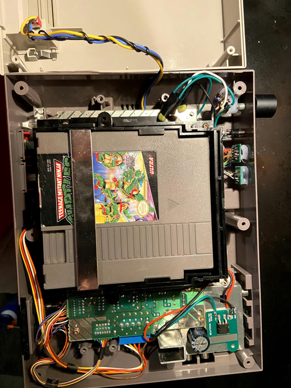
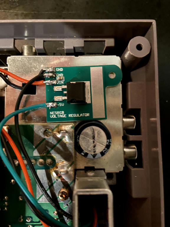
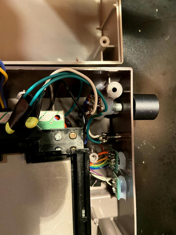
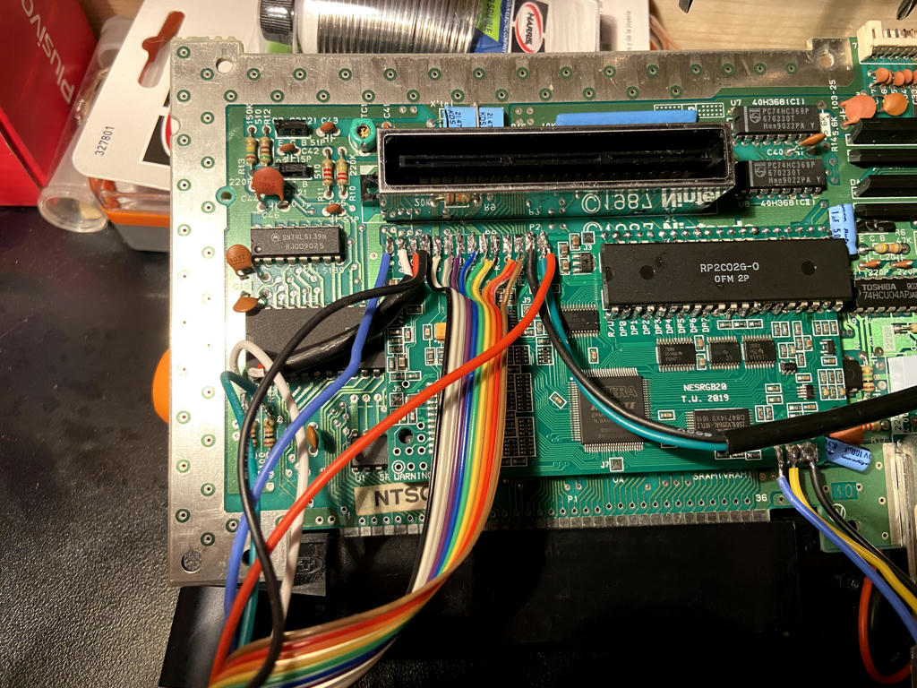
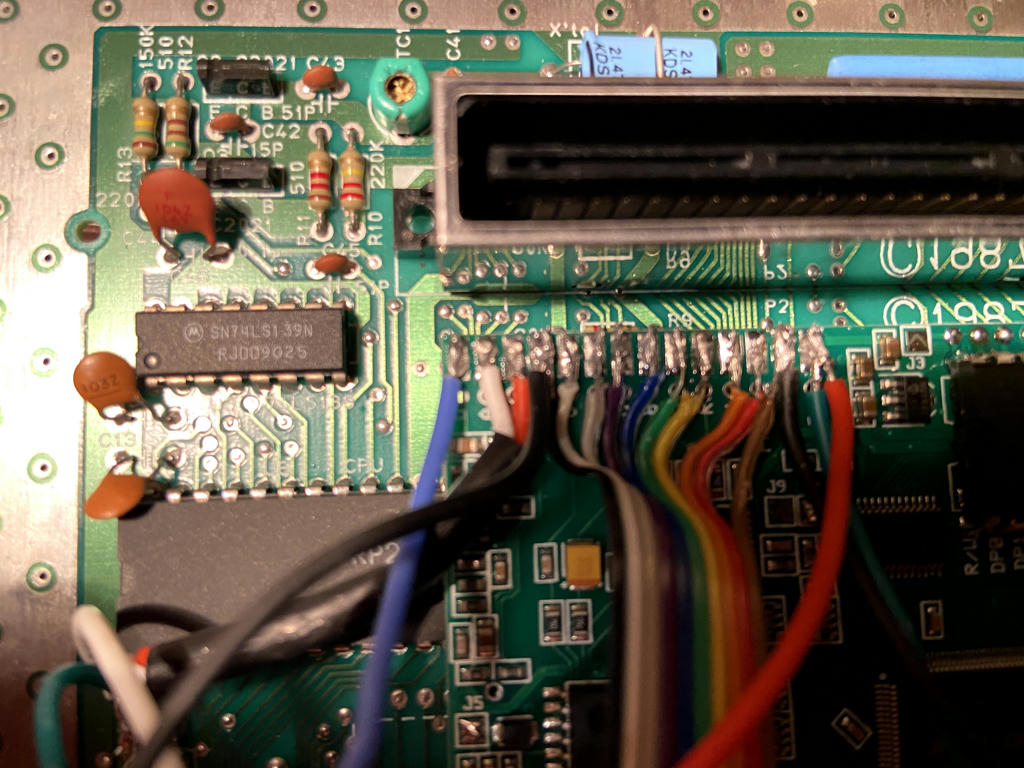
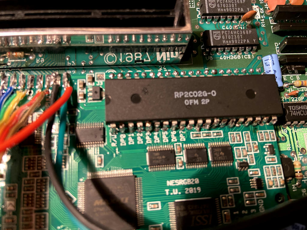
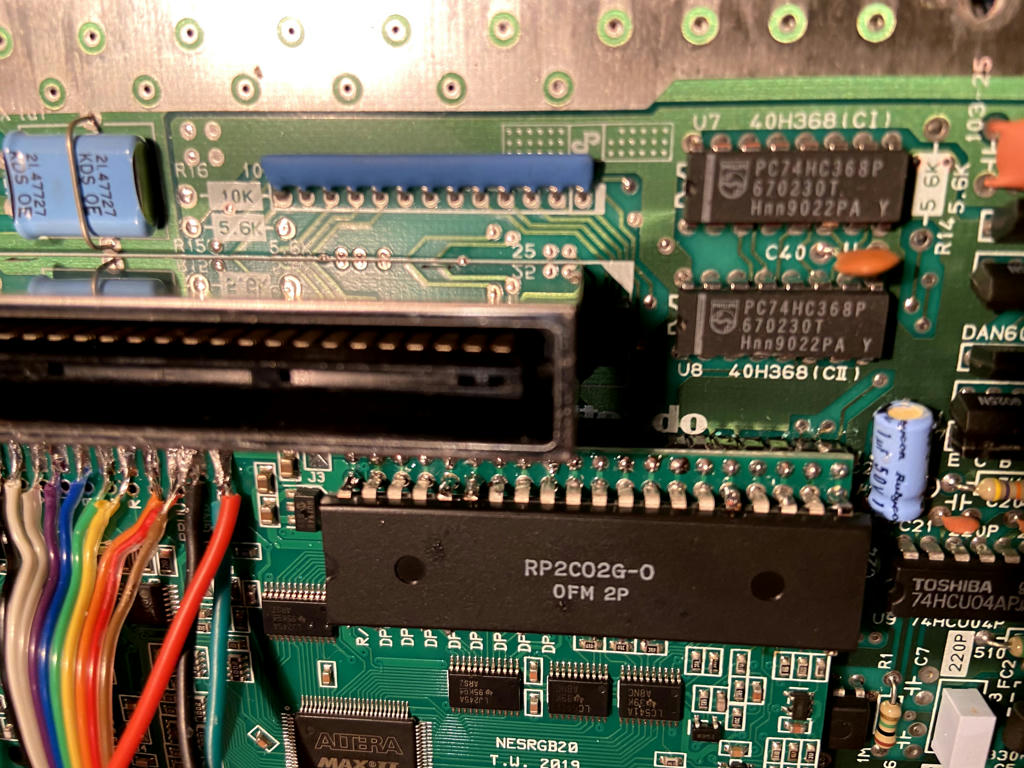
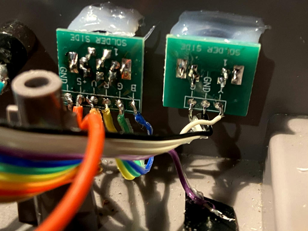
Here's my pictures, sorry this is huge..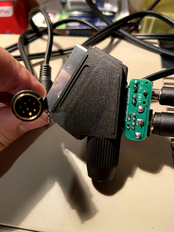
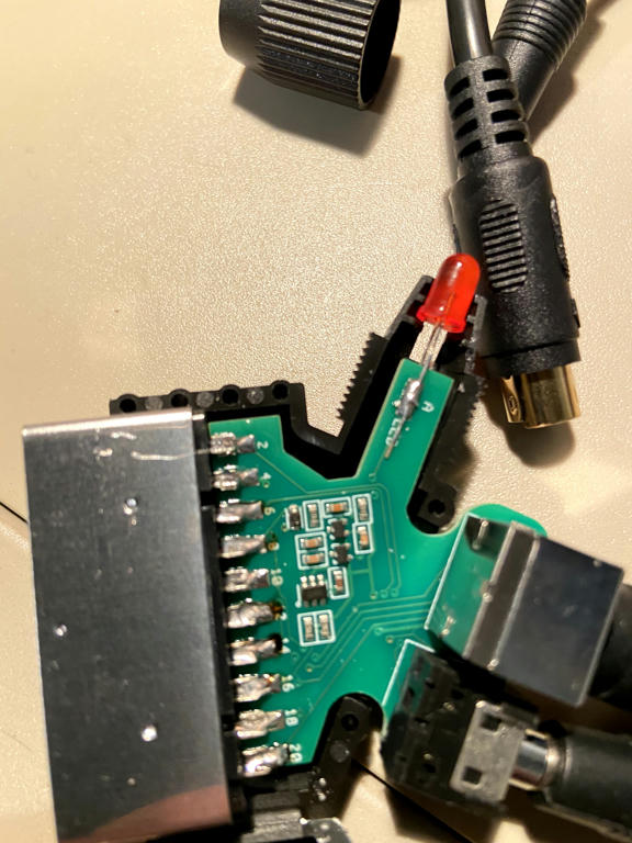
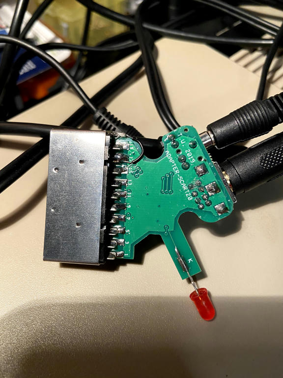
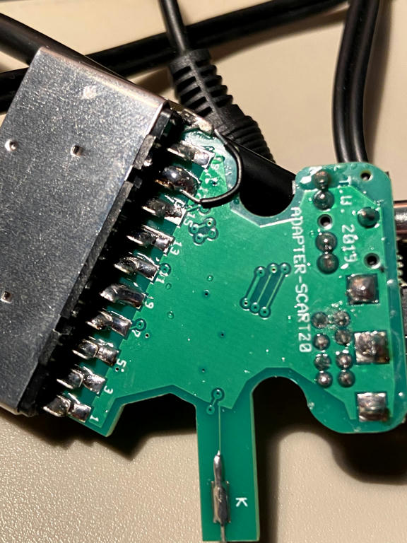
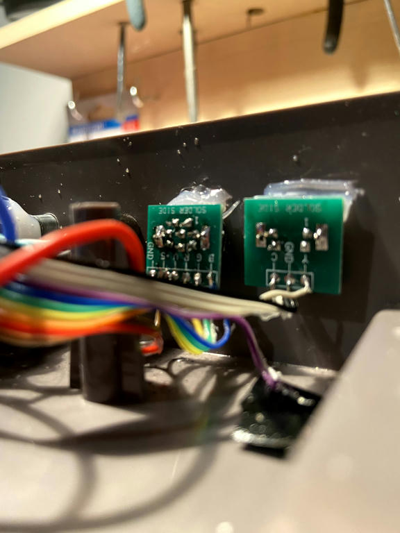 Thanks for your help
Edit: So I tried adding grounds from the nesrgb to the main board and also measuring the blanking signal, 4.8V to blank. Also found that if I crank up the bightness I can see a ghost of an image, could be blead through from the C-sync. Works great over S-Video, does that mean all my PPU connections are alright? Much like other newbs, removing the PPU was a challenge.
Here's my pictures, sorry this is huge..
Spoiler
Edit: So I tried adding grounds from the nesrgb to the main board and also measuring the blanking signal, 4.8V to blank. Also found that if I crank up the bightness I can see a ghost of an image, could be blead through from the C-sync. Works great over S-Video, does that mean all my PPU connections are alright? Much like other newbs, removing the PPU was a challenge.
-
Tempest_2084
- Posts: 593
- Joined: Tue Feb 04, 2014 3:05 pm
Re: NESRGB board available now
I'm attempting to solder a wire to my NESRGB board in order to mix in the expansion audio (Wolff's mod: http://www.firebrandx.com/edn8tonesrgb.html). As I have a v1 version of the board and not a v2, I contacted the board's creator (Tim) and was given a diagram showing three different points where I can do this on the v1 board. I've never attempted to solder to something this tiny before. Any tips? I'm thinking about trying for the top component as it's not quite so flat to the board and I think I actually have a chance of getting the wire in there without making a solder bridge to an adjacent component.

Re: NESRGB board available now
I would assume that if you borked your PPU, then you would get no video output over s-video. Unless someone here contradicts me, I think it's safe to assume that the problem is downstream from there. That's what I would do.MiteWiseacre wrote:Works great over S-Video, does that mean all my PPU connections are alright? Much like other newbs, removing the PPU was a challenge.
One thing I don't understand is what all those cables are for on you Scart cable. I have an NESRGB, and I use a scart cable that only has output capacitors on the color lines and that's it. There's nothing else in there. Looks like maybe yours has some buffers or something. Is that a power input or an audio output?
Maybe you should lose the fancy cable and see if it will output with a fleabay cheap-o like I'm using. Just cut off the nintendo multi out connector and hook up a din to it. If there's something wrong with your cable, that would solve it.
Also, I would check the connections for the pallet switch. It would default off if you have in the wrong position.
I think it's either going to be a connection issue, your cable, or you have an issue with the NESRGB itself.

Re: NESRGB board available now
You should check with a multimeter but I imagine all three of those points are connected, so it shouldn't matter even if they do get bridged. Shouldn't be too hard though, just pick any of the points, add a bit of solder and slide a small tinned wire into the blob, then remove the iron and hold the wire there for a second or two just to allow it to set.Tempest_2084 wrote:I'm attempting to solder a wire to my NESRGB board in order to mix in the expansion audio (Wolff's mod: http://www.firebrandx.com/edn8tonesrgb.html). As I have a v1 version of the board and not a v2, I contacted the board's creator (Tim) and was given a diagram showing three different points where I can do this on the v1 board. I've never attempted to solder to something this tiny before. Any tips? I'm thinking about trying for the top component as it's not quite so flat to the board and I think I actually have a chance of getting the wire in there without making a solder bridge to an adjacent component
-
Tempest_2084
- Posts: 593
- Joined: Tue Feb 04, 2014 3:05 pm
Re: NESRGB board available now
I manage to get everything connected but I'm not getting the expansion sound through the board output. Either there's more to it that I'm missing or I didn't get it soldered correctly on the board. Unfortunately this is beyond my skills to diagnose I think. I'm using Wolff's mod BTW (http://www.firebrandx.com/edn8tonesrgb.html)
EDIT: Turns out whoever did my mod forgot to wire up the A, B, and O on my NESRGB board and connect it to my multi-out. That's why I'm getting no expansion audio.
EDIT: Turns out whoever did my mod forgot to wire up the A, B, and O on my NESRGB board and connect it to my multi-out. That's why I'm getting no expansion audio.

Re: NESRGB board available now
Hi everyone,
Just a quick query. I recall sometime ago that the Everdrive N8 Pro had some compatibility issues with NES RGB systems (and Hi-Def NES for that matter), it seemed to be mainly ones with the IGR board installed. The conversation over on the ED forums has gone somewhat quiet but it's suggested there was a new rev that sorted things out. Does anyone here have the N8 Pro with a NESRGB + IGR board, specifically in an AV Famicom who can comment please? I'm hoping to get mine modded in the near future and get the N8 Pro but I'm unsure if I should get the IGR in case there are any issues.
If anyone that has the setup could could comment it would be much appreciated.
Many thanks.
Re: NESRGB board available now
Can the NESRGB mod be installed alongside the Hi-Def NES mod on an AV Famicom? Also, is the Hi-Def NES Mod the only way to get digital audio?