If you're reading this, you probably already know that although a Sanwa JLF joystick is fantastic for fighting games
(the best in my opinion), it's pretty awful for shmups/space shooters/etc., as well as some other genres.
For those who may have been redirected here from somewhere else, I'll explain why:
Engage distance is the distance you have to move the stick before it engages the microswitch, meaning that the game reads a directional input. Throw distance is the distance you can move the stick before it hits the restrictor, meaning that it can't be moved any further. Both the engage and throw of a stock JLF are much too large for optimal control with shmups. A smaller engage and throw distance naturally allows for quicker movements, so a shmup fan will often opt for a Seimitsu stick.
I've created a fairly simple mod that significantly reduces the engage and throw of the JLF, to make it more suitable for shmups; and it can be done in an evening, for under $10. IMHO, a JLF with this mod is not only the best option for shmups, but also one of the best all around joysticks. It especially stands out for difficult platformers, like Megaman, or Hagane. If you're still wondering what the advantage of doing this is, considering the following:
Sanwa joysticks are top of the line in terms of quality, have extremely smooth movement, and are extremely accurate and reliable. Here is a quote from independent joystick reviewer Kowal:
"When it comes to quality and aesthetics, Sanwa is the undisputed leader. In every aspect, their products are top quality. You may not like Sanwa due to their specific properties," (engage and throw) "but the rest of the joystick producers are at least a class behind in quality."
http://www.kowal.itcom.pl/ArcadeParts_p ... LFTP8Y.htm
In the joystick comparison at Slagcoin.com (another independent reviewer), the Sanwa JLF and JLW were the only joysticks to receive a Pivot Quality rating of "Very High," Seimitsu's received a "Medium" rating. The reviewer also commented that about Seimitsu's that "Their parts cost less than Sanwa parts, and do have a lower quality in a few areas."
http://slagcoin.com/joystick/attributes_brands.html
Furthermore, Seimitsu sticks use levered microswitches, meaning the joystick presses a lever, which then actuates the microswitch. The bend of the levers will change the engage distances, and there is a lever for each of the four directions, making it difficult to set all four directions to a consistent engage distance. This is not necessarily set perfectly from the factory, and it can change slightly over time. JLF's avoid these problems with more accurate leverless microswitches.
Engage and throw are the only problems for the otherwise superior JLF, once this is corrected, it can really be superb for shmups. The mod below reduces engage and throw while maintaining the smoothness, accuracy, and quality, of the stock joystick. It is also easily reversible to return to stock.
Technical Details of the Mod
Code: Select all
       | JLF  | LS-32 | LS-40/56 | LS-33  | Modded JLF
-------+------+-------+----------+--------+-----------
Engage | 6 mm | 5 mm  | 4   mm   | 3.5 mm | 3.25 mm
-------+------+-------+----------+--------+-----------
Throw | 8 mm | 7 mm | 7.5 mm | 7 mm | 6.25 mmAll measurements are taken using a square restrictor, which is what I recommond using. More details about measuring these properties can be found here:
http://www.kowal.itcom.pl/ArcadeParts_pliki/artMET.htm
Reducing engage and throw is accomplished simply by moving the actuator, microswitches, and restrictor away from the pivot point.


On the left is a stock JLF, on the right is a modded one. Simple geometry will tell us that moving these parts further from the pivot point will cause the actuator to contact the microswitches and the restrictor with less movement at the ball top.
This mod also retains the spring tension of the stock JLF, but I would recommend tightening it a bit for shmups. See optional step 14b below for more info.
Notes on Mounting
No changes to the mounting plate are made in this mod, and the underlying body is not made any wider in either direction, so any control panel or case that has already been designed for a JLF should not need any further modification to accommodate it.

This is the bottom of the JLF after modding. Normally the shaft of the stick is what protrudes furthest away from the body of the stick, therefore dictating the necessary depth of the control panel or case. As you can see above, the screws added in the mod don't protrude any further than the shaft. The only things that do are the two tabs extending from the restrictor, which are unnecessary, and can be cut off.
Instructions
This mod shouldn't be too difficult, but if you're unsure if you're up to it, take a look at steps 2-5. These are by far the hardest steps. If you can handle them, the rest will be easy. If not, seek help from someone who is mechanically inclined.
Supplies Needed (aside from the stock JLF itself, and simple tools)
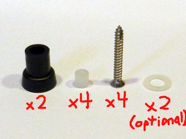
2 Sanwa JLF P-5 Actuators - These will be referred to as "stock actuators" in the instructions. One comes with the joystick, but I would recommend buying at least two more. Two will be modified, so a third is needed to return to stock. You may also a want a few more extras on hand, in case you mess up the modification (see steps 2 and 3). These are available at FocusAttack.com for 90 cents US each:
http://www.focusattack.com/sanwa-jlf-p-5-actuator/
4 Cylindrical Nylon Spacers - 0.25" Outside Diameter, 0.14" Inside Diameter, 0.25" Long - These will be referred to as "microswitch spacers" in the instructions. All dimensions are in inches. These are available at Lowe's for 56 cents US per 2. Someone will have to chime on other sources online, or outside the US. They shouldn't be too rare.
4 Screws - #7, 1-1/4" Long - These will be referred to as "screws" in the instructions. Also available at Lowe's for 86 cents US per 4. They may be called "hinge screws," and be hidden in a specialty drawer, away from the other screws. #7 is not a common size screw. #8 screws may work if necessary, #6 will be too small.
2 Nylon Washers - 1/2" Outside Diameter, 9/32" Inside Diameter, 1/32" Thick - These will be referred to as "spring washers" in the instructions. Also available at Lowe's for 92 cents US per 4. This is an optional part (see optional step 14b).

I would recommend lubricating your joystick while you have it apart, even if it's new. Dow Corning Molykote 44 Light is a type of grease which supposedly has the same chemical makeup as the Japanese Shin-Etsu grease that comes in these sticks. It's more commonly available outside Japan, and may be cheaper, especially for shipping.
A small plastic-bristled brush will be useful for applying it neatly.
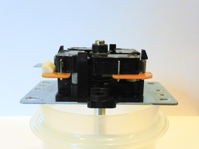
Part 1: Disassembly
Step 1: umm... Take it Apart
Start by taking apart the stock JLF.

The restrictor does not need to be separated into two pieces.

The microswitches do not need to be removed from the PCB or opened up.

The plastic base does not need to be removed from the mounting plate.
Aside from these parts, the joystick should be completely disassembled, down to every possible piece. Take note of how things fit together as you're doing so. You may also want to clean off all the old grease.
Part 2: Modification
Step 2: Create the Actuator Spacer

On the left is a stock actuator, on the right is a modified actuator, which will be referred to as the "actuator spacer." Creating the actuator spacer requires shortening the thinner side of the stock actuator by exactly 7/32". The total height of the stock actuator is 43/64", meaning that the total height of the actuator spacer should be 29/64" after modification.
Begin by cutting some material off with a hacksaw. It will be hard to cut exactly straight, so don't try to cut off the full 7/32". Be sure to account for the width of the blade, and leave an extra 1/16" to 1/8".
Use a flat file to remove the remaining material. Be sure to position it squarely, making sure that the top is being cut level. To check this, hold the actuator down on a large flat surface, with the surface you're working on face down. View it from the side and turn it slowly. If it's not level it will wobble as it rotates.
Shortening the actuator by the right amount and making it level is very important. File off a little bit at a time, stopping frequently to check if it's level, and if you've reached the specified height. Do not use any power tools in place of the flat file, as it will be easy to take off too much material from the soft plastic.
Step 3: Create the Short Actuator
Creating the short actuator requires the exact same process as the actuator spacer, except that the stock actuator must be shortened by exactly 1/4", resulting in a total height of 27/64".
I've recommended attempting the actuator spacer first, so that if too much material is taken off it may still be usable for the short actuator, which has a shorter total height.
Step 4: Drill the Restrictor and the Microswitches
Set the restrictor on top of the microswitches, aligning the pegs and holes as you would for normal assembly.

Using an 11/64" bit, drill straight down through the four holes notated, through both the restrictor and the microswitches. A drill press will make this easier, but it can be done with a handheld drill. Set the pieces on a piece of wood, and make sure to drill straight down. If you press lightly, the small holes that are already in place will naturally center the bit.

After drilling, the screws should fit through the new holes and turn freely.
Step 5: Modify the E-Ring

If you set the E-Ring on top of the short actuator, you'll notice that it sticks out over it a bit. This can't be allowed, as it will grind on the restrictor, which is only supposed to make contact with the short actuator.

On the left is a stock E-ring, on the right is a modified E-Ring. Use a flat file to grind down the edges, until its a little smaller than the top of the short actuator. Use a pair of plyers or vise grips to hold the E-ring, and keep it from bending.
Part 3: Assembly
Step 6: Lubricate

Apply a thin film of grease to the pivot area. This is the most important part to lubricate. Be sure to fill the grooves with extra grease.
Step 7: Install the Pivot Cylinder

Step 8: Install the Shaft

You'll notice that I assemble the stick with the balltop on, this was just to make things easier to hold on to.
Step 9: Flip it Over

Step 10: Install the Pivot Washer

I highly recommend super-gluing this down.
If there is a good amount of grease on the spring holder, it will pick up one side of the pivot washer out of its indentation as it moves over it. Then it will hang up as it gets pressed back down. This will cause an annoying popping feeling at times while you're moving the stick around, and it can be pretty bad after this mod. Gluing it down will eliminate the problem and ensure completely smooth operation. There's not any reason its needs to be taken back off again anyhow.
Any super glue that is designed to bond to both plastic and metal will work; JB weld, Krazy Glue, etc. Just make sure to clean off any excess that squeezes out.
Step 11: Lubricate Again
Apply a thin film of grease over the pivot washer and the shaft.
Step 12: Install the Spring Holder

I apologize for the poor picture here. It's the small black piece that goes under the spring. Reinstall it the same way it came apart.
Step 13: Install the Spring

Step 14: Install the Actuator Spacer

Optional Step 14B: Increase Spring Tension

One or two spring washers can be placed here to slightly increase the spring tension. Omitting the washers will retain the stock spring tension. Using more than two washers will overcompress the spring and cause it to bind up. Don't use more than two.
If you need more tension, using springs from other joysticks will have the same effect as they would on a stock JLF. A Seimitsu LS-32/LS-40 spring or an LS-55 spring is a good choice, either in place of the JLF spring or along with it.
Some may prefer to add some tension with spring washers, while others will prefer another spring. Either way, I would not recommend playing shmups with just the stock JLF spring tension.
Step 15: Install the Short Actuator

Step 16: Install the Modified E-Ring

Compress everything down and slip on the E-Ring. The E-Ring may need to be pinched together if it has become weak from being thinned down. Once it's in place the force pushing up from the spring will keep it in place.
Step 17: Lubricate One More Time
Apply a thin film of grease over the short actuator. This is probably the least commonly lubricated part, but I have found tiny bits of black on the red microswitch tips, indicating wear (on stock JLF's, before I even started modding). A little bit of grease here will prevent this.
Step 18: Install the Microswitch Spacers

There will be small black pegs to place the microswitch spacers over in the locations shown.
Step 19: Install the Microswitches

Place the microswitches over the spacers, making sure that all four spacers are squarely contacting the microswitches. The left picture shows the correct installation, while the right picture shows the spacer hung up on the PCB. Check all four sides to make sure this isn't happening.
Step 20: Install the Restrictor

Set the restrictor on top of the microswitches, aligning the pegs and holes. The black clips will no longer reach up far enough to lock it in place. This is where the screws come in.
Step 21: Install the Screws

Tighten the screws slowly and evenly on all four sides, allowing the bevel of the screw heads to center the restrictor. Tighten them just barely snug, as it won't be difficult to overtighten and strip the black plastic base, or crack the restrictor.
THAT'S IT, GO PLAY!


 | My games -