Some info from Micomsoft (via twitter) regarding non-standard timings (deviating from NTSC).
Up until XRGB-3, they used a fairly simple A/D converter that was able to handle
these non-standard timings easily, but with the XRGB-Mini supporting HDMI and RGB,
they needed to switch to a complex and high cost A/D converter; thus, adding
support for non-standard timings is going to require some complicated calculations,
which haven't been looked into at this time but may be considered for future firmware updates.
XRGB-mini Framemeister
Re: XRGB-mini Framemeister (now available !)
Yeah xmen vs street fighter is what I'm testing with. No dropouts just that problem, so I'll just make up a little adapter.Konsolkongen wrote:Actually, when looking at Saturn schematics it looks like it needs both a 75ohm resistor and a 220uF capacitor on the sync line. Just thought you should know, in case you suddenly experience drop-outs on your Saturn. However it has been working fine so far with just the cap hereI had the X-Men vs Street Fighter intro running for about an hour yesterday, and that has always been a guaranteed drop-out hell when using composite video as sync.
-
Konsolkongen

- Posts: 2315
- Joined: Fri May 16, 2008 8:28 pm
- Location: Denmark
Re: XRGB-mini Framemeister (now available !)
You should put it in the cable, because this isn't a problem with the Mini. It's a problem with C.sync on these newer Saturns. The same problem also showed when I connected it to my XRGB-3 and TV directly.

Re: XRGB-mini Framemeister (now available !)
If they add PAL support I'd order one right awayadding support for non-standard timings is going to require some complicated calculations, which haven't been looked into at this time but may be considered for future firmware updates.
OSSC Forums - http://www.videogameperfection.com/forums
Please check the Wiki before posting about Morph, OSSC, XRGB Mini or XRGB3 - http://junkerhq.net/xrgb/index.php/Main_Page
Please check the Wiki before posting about Morph, OSSC, XRGB Mini or XRGB3 - http://junkerhq.net/xrgb/index.php/Main_Page
-
Konsolkongen
- Posts: 2315
- Joined: Fri May 16, 2008 8:28 pm
- Location: Denmark
Re: XRGB-mini Framemeister (now available !)
Isn't PAL50 a standard timing?
Re: XRGB-mini Framemeister (now available !)
Probably not if you're living in Japan I guess.
OSSC Forums - http://www.videogameperfection.com/forums
Please check the Wiki before posting about Morph, OSSC, XRGB Mini or XRGB3 - http://junkerhq.net/xrgb/index.php/Main_Page
Please check the Wiki before posting about Morph, OSSC, XRGB Mini or XRGB3 - http://junkerhq.net/xrgb/index.php/Main_Page
-
Konsolkongen
- Posts: 2315
- Joined: Fri May 16, 2008 8:28 pm
- Location: Denmark
Re: XRGB-mini Framemeister (now available !)
Of course, but it is a standard, and according to Fudoh fully supported by the hardware. So I assume it would be easier to add support for PAL50 than some obscure 54hz arcade board.
Unrelated, but does the Mini accept 24kHz inputs?
Unrelated, but does the Mini accept 24kHz inputs?
Re: XRGB-mini Framemeister (now available !)
Gradius IV does not work, so I would guess that 24KHz is not supported.

Re: XRGB-mini Framemeister (now available !)
alamone wrote:Some info from Micomsoft (via twitter) regarding non-standard timings (deviating from NTSC).
Up until XRGB-3, they used a fairly simple A/D converter that was able to handle
these non-standard timings easily, but with the XRGB-Mini supporting HDMI and RGB,
they needed to switch to a complex and high cost A/D converter; thus, adding
support for non-standard timings is going to require some complicated calculations,
which haven't been looked into at this time but may be considered for future firmware updates.
That explains a lot, thanks for sharing. Which is that twitter account?
I also tested Street Fighter 1 and it couldn't sync either, since it isn't standard timming either Checked Moonwalker again after readjusting SuperGUN voltages and still blue screen. The mini shows 57.24 hz.. so it figures.
Re: XRGB-mini Framemeister (now available !)
@famitakunArtemio wrote: That explains a lot, thanks for sharing. Which is that twitter account?
By the way, my account is @alamone, feel free to follow.
-
franjipane
- Posts: 36
- Joined: Wed Feb 25, 2009 11:30 am
Re: XRGB-mini Framemeister (now available !)
Bought 2 RGB cables this week to get my Japanese Saturn and Super Famicom working with the Mini. Neither work when plugged into the mini, both work perfectly fine plugged straight into my TV. Damn Ebay, both were supposed to be Japanese, might try and resolder them.
-
Konsolkongen
- Posts: 2315
- Joined: Fri May 16, 2008 8:28 pm
- Location: Denmark
Re: XRGB-mini Framemeister (now available !)
Do you live in Europe, and is your TV European too? In that case, yes the cables are SCART and not Japanese RGB21.
But the Mini's RGB input works fine still? If you connected a SCART cable to a XRGB-3 directly it could fry the input
But the Mini's RGB input works fine still? If you connected a SCART cable to a XRGB-3 directly it could fry the input
-
franjipane
- Posts: 36
- Joined: Wed Feb 25, 2009 11:30 am
Re: XRGB-mini Framemeister (now available !)
Yea I live in England with a normal Pal TV, both Ebay listings said they were Japanese cables so I'm pretty annoyed. I hope they haven't fried the input, I have nothing else to test it with at the moment. It have hooked up my PS3, 360 and Wii to the mini and they all look great, not really what I bought it for though 
-
Konsolkongen
- Posts: 2315
- Joined: Fri May 16, 2008 8:28 pm
- Location: Denmark
Re: XRGB-mini Framemeister (now available !)
Why don't you resolder the RGB cable that comes with the Mini and just use EU SCART cables from now on? I did that, and it's much easier IMO
-
franjipane
- Posts: 36
- Joined: Wed Feb 25, 2009 11:30 am
Re: XRGB-mini Framemeister (now available !)
I kind of wanted to keep that breakout cable original, but I might as well it'll save so much time, and I'm really awful at soldering!
-
retr0gamer
- Posts: 34
- Joined: Wed Dec 21, 2011 1:23 pm
Re: XRGB-mini Framemeister (now available !)
I'm trying a different tactic by preserving that cable, and taking some other male -> male SCART cable, cutting off the one end, and attaching a mini-din 8 plug on the other end and wiring it up like in the diagram. Then it goes straight from my SCART switch with no additional connection involved.
-
Konsolkongen
- Posts: 2315
- Joined: Fri May 16, 2008 8:28 pm
- Location: Denmark
Re: XRGB-mini Framemeister (now available !)
It's fairly straightforward to do. And the wires are easy to tell apart as well:
So they really made it easy for us
Connect it like this:
As you might see there isn't enough black wires for all the GND points. So you have to solder the thick white wires from one black wire to another pin. If your soldering skills aren't that good I would probably ask someone else to do it, just in case
Code: Select all
Thin red:                  Audio R
Thin white:                Audio L
Blacks (and thick whites): GND
Yellow:                    Sync
Pink:                      Red
Green:                     Green
Blue: BlueConnect it like this:
Code: Select all
Even numbered side:

Pin: Wire:
2  Thin red
4  GND
6  Thin white
18 GND
20 Yellow

Uneven numbered side:

5  GND
7  Blue
9  GND
11 Green
13 GND
15 Pink
17 GND
21 GND
Re: XRGB-mini Framemeister (CSYNC INFO and a good read)
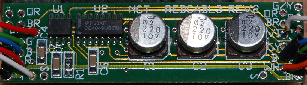
This info is from 1992... just about 20 years ago... and here we are fussing over how to get sharp video from a SNES and sync compatibility. I have the RGB interface boards made by Redmond Cable for the PS cables. However, Redmond Cable no longer deals with proprietary RGB game cables, but they still build custom cables!
RGB Video Fundamentals
Don Lancaster's Hardware Hacker, June, 1992
I have recently been working with Dennis Carper of Redmond Cable in interfacing all sorts of video games to all types of leftover surplus computer monitors. So, I guess it might be a good time to review some of the fundamentals of RGB monitors.
The reasons we go to the separate red-green-blue route in the first place are for picture quality and for picture resolution. Regardless of how much trouble you go to, it is simply not possible to glomp onto the antenna terminals of an ordinary tv set and display anything even remotely near what is needed as a bare minimum for all of today's color computer displays or premium arcade video games. The needed bandwidths and scan rates are simply not there.
Unlike broadcast signals (such as NTSC or PAL or SECAM), there are no universal standards being used for RGB monitors. If it has three separate video lines on it, it is an RGB system. Period. Thus, you will have to be very careful what your video source and your video monitor are capable of before you try to connect them.
The simplest of RGB systems use "TTL" monitors. These do not accept video as such. Instead, they receive digital logic signals which turn their red, green, and blue beams entirely off or on. Thus you can only get eight possible colors. All eight of which are always fully saturated. Some TTL monitors include a fourth brightness line that gives you a choice of "full" or "half" bright, upping the apparent color total to sixteen.
Instead, on a linear RGB monitor, all shades of all colors are possible. Linear monitors need much more in the areas of video amplification and linearization (or gamma correction) circuits. Obviously, linear monitors are required for "rcal" video from a cable or broadcast source, or anytime else you need a very wide range of hue and saturation values.
Most linear monitors are not too fussy over accepting interlaced scans, as get used on standard tv; or the non-interlaced scans, as must get used on most data displays. But linear monitors are extremely fussy over their horizontal scan rates. Ordinary TV uses the horizontal scan rate of 15.735 kilohertz for color or 15.750 kilohertz for black and white. Most computer scan rates are double this, up in the 32 kilohertz range. And premium systems can have scan-rates of 80 kilohertz or higher.
Unless your monitor is carefully designed to be a multi-syncing type, it will only accept a very limited horizontal scan rate range. Thus, there is no way you could use an ordinary broadcast RGB monitor to display a Mac or VGA output. It flat out cannot operate at the higher scan rates.
One of the ruder surprises to Apple IIgs people downgrading to a Mac LC is that their old color monitor will no longer work. Their IIgs monitor is a broadcast-only style, while those LC video scan rates are on up in the 30 kilohertz range. Fortunately, a simple jumpering option (which we saw a few columns back) lets the LC use an ordinary and cheaper VGA monitor.
Thus, you have to be sure that your intended RGB monitor is capable of accepting the horizontal scan rates provided by your video source. Some combinations simply will not work.
A final major consideration is the monitor's resolution. The resolution is set by the video bandwidth and the pitch of the color bars or dots on the screen. Images will smear if you try to view them on any monitor whose resolution is too low for the intended application. The results can end up anywhere from a slight eyestrain to totally un-viewable.
So, a second rule: Make absolutely certain you test and use any monitor in its intended final use before you actually pay for it.
Your video lines could be high impedance cables if the runs are short, or terminated ones (usually 75 ohms) for longer distances. A fair amount of power is required to properly drive a terminated video cable. Maxim is one good source for video drivers. Video cables are best done either as fully shielded, or, at the least, as twisted pairs. If any separate grounds are provided, they should be used as they were intended.
If your video source has any dc offset present (such as the emitter follower outputs of a Super Nintendo, then you must provide for a capacitor coupling between your source and the monitor. Very large capacitors are recommended, of at least 220 microfarads or more. But these may already be built in, so check first.
There are several synchronizing options used in RGB systems. Some systems tack sync signals onto the green channel and later strip them off. But most systems have separate sync line(s) which deliver the horizontal, vertical, or composite sync signals.
To further confuse matters, sync lines can be smaller one volt signals at analog levels, or can be TTL or CMOS compatible. Others may be at TTL levels, but end up too small for CMOS and too weak for TTL. We saw a 'user Nintendo workaround for this last month using a simple 680 ohm resistor to ground.
Typical sync lines are active low meaning that your sync tips are at ground. But a few (especially earlier Commodore products) demand an active high composite sync.
Figure two shows you how to use several inverters to amplify low level sync signals into full CMOS and TTL compatibility having your choice of either active low or active high sync tips. Your first stage can be a biased inverter amplifier having a gain of twenty or more. The second inverter further cleans up your now-digital waveform, while the third and fourth stages act as inverters or drivers.
If you try this linear amplifier stunt with other CMOS gates or inverters, be sure to use "single stage" unbuffered (UB) versions; other buffered ones may have too much gain and could oscillate.
More details in my CMOS Cookbook.
Our sync separator and universal video interface from two months back is easily modified to provide suitable sync amplification for the Neo-Geo or Super Nintendo. Sound is separately dealt with on a RGB system. Sometimes, there will be no sound at all. One clue here is the absence of any volume control. Radio Shack makes a neat little $11 lab amplifier that can sit in for you. Other options are monophonic sound, stereo sound, or a multiplexed stereo sound accepting R - L and R - L inputs. Super Nintendo uses multiplexed sound.
If you forget to de-multiplex, one channel will sound monophonic, and the other might sound awfully tinny and just plain "wrong". To properly de-multiplex, you add the two signals together to get the right channel and subtract them to get the left one.
Regardless of your sound system, totally shielded audio cables are a must. Ideally, they should be totally separate from all your video cables, owing to the strong "hum" and "buzz" induced by vertical rate signals.
So, what can you interface to who? Use your oscilloscope to view all the normal outputs of your video source run in their intended way. Then do the same for the "normal" inputs to the monitor. Some hints: To tell if a source is capacitor coupled, briefly connect a 470 ohm resistor between the pin and ground or +5. If the scope display bounces around and slowly drifts on back, you are ac capacitor coupled. If it remains in the initial position (or possibly gets slightly smaller), then you are dc coupled. Be sure to note any fixed offset voltage.
To find out your source impedance, note that any resistive load equal to your source impedance will drop your output signal level to one half of the open circuit value.
--------------------------------------------------------------------------------
Video Sync Separation
Don Lancaster's Hardware Hacker, March, 1992
Another popular helpline topic is video interface. And the number one ongoing request is for a simple and effective sync separator. The sync separation process lets you take your normal composite video signals and extract those horizontal and vertical synchronizing pulses from it.
The most obvious use for a sync separation is to let you clearly view video signals on your oscilloscope. Without a field or frame reference, all you will see is a blur. Other uses for sync separation do involve stripping closed captioning or other data off specific horizontal lines present during vertical retrace, grabbing stock quotes, inserting windows, pattern generators, title overlays, wiping and fades, color keying, and other special effects. Or simply adding a pair of crosshairs.
Figure one shows you a simple and low cost circuit I’ve worked up that can combine both an effective sync separator and a low cost universal video interface card. The key chip is the National LM1881 sync separator mini-dip. You take your usual one to two volt positive going sync=ground video signal and capacitor couple it to pin 2. The chip extracts the composite video and produces the active low TTL/CMOS compatible composite sync output on pin 1.
Several other pins on the LM1881 provide other functions that you may find handy. Pin 3 gives you a vertical sync reference as one single pulse without the usual teeth or serrations. This is the one you will usually want to lock your scope to. Pin 5 is a burst gate that gives you a slightly delayed horizontal sync pulse that can be used to extract any NTSC (Never The Same Color) chroma burst info.
An RC network found on pin 6 is intended to create a default vertical sync in absence of a true NTSC video input. This is handy for the "almost" NTSC common to the computers and video games. The time constant can be shortened for higher scan rates; see the National data sheet for details.
Finally, pin 7 lets you pick out the odd and even fields of an interlaced NTSC frame. This output is active only when the input composite video has a full interlace. Advanced color editing is one possible use.
An external source of the usual five volts DC is needed. Since the current is only seven milliamperes, just about any old supply will do. As usual, keep the power bypass caps real close to your chips.
Several other features on the circuit are handy for special video interface cables. The three large capacitors let you couple red, blue, or green video off emitter follower outputs and then connect them to RGB monitors. A 75 ohm resistor is handy for terminating cables. And a logical high signal is useful for such things as enabling the sound on certain receiver/monitors. By itself, the inverter is handy for converting active low sync into active high and vice versa. While most of the video systems do use active low sync, Commodore and one or two of the others may not.
The printed circuit layout is shown you in figure two. Empty boards, kits, tested circuits, and both stock and custom interface cables are available from Redmond Cable. You can call or write them for a current price list. I’ll also post this layout on GEnie PSRT, so you can easily create your own accurate version without needing any photo work. See HACKFG51.PS.
You may want to keep some empty or partially populated boards on hand to solve special cabling and interface uses. The large runaround ground on the outside is especially handy for shielded cable terminations.
For this month’s contest, just tell me about an unusual or off-the-wall use for a sync stripper circuit. There will be all of those usual Incredible Secret Money Machine II book prizes, along with an all expense paid (FOB Thatcher, AZ) tinaja quest for two going to the very best of all. As usual, send your written entries directly to me at Synergetics, rather than over to Radio-Electronics editorial.
Let’s hear from you.
--------------------------------------------------------------------------------
Nintendo-to-Anything Interface
Don Lancaster's Hardware Hacker, March, 1992
As figure three shows us, there’s a very interesting Multi-Out connector on the back of those Super Nintendo game machines. This gives you lots of alternate video and sound output formats that you might find handy.
For instance, you can go to a RGB monitor for sharper images and better colors. Or add total stereo sound or Super VHS improved resolution.
Or, you may want to hang any old tv-compatible color monitor plus a pair of headphones on the machine to silence kids and keep them off your main prime time television set.
Let us see exactly what is on this connector and how to use it. By a special arrangement with Redmond Cable, all the connectors, the above interface kit, and special and stock cable solutions for almost any Super Nintendo interface are available. The Multi-out connector is really six-over-six edge traces on a double sided circuit board. Looking at the rear, the traces are odd numbered 1,3,5,7,9,11 on the top, going right to left. And the similar pins are even numbered 2,4,6,8,10,12 on the bottom, again going from right to left. Both pins 7 and 8 are grounds. The pair make terminating several shielded wires much easier.
A +5 vdc output is provided on pin 10. It appears to be capable of driving at least 50 milliamperes. But you shouldn’t suck the poor machine dry, and you should very carefully bypass and filter any use of this supply.
There are a pair of sound outputs. Pin 11 is your choice of monophonic sound or a (L + R) matrixed stereo.
Note that "left" plus "right" equals "both". Pin 12 is (L - R) matrixed stereo. These signals are capacitor coupled and are the proper size for your usual audio inputs on a hi-fi receiver or computer monitor.
Note that some computer monitors have a sound capability and some do not. The easiest way to tell is to find an obvious volume control located somewhere on your set. No volume control, no sound. Other monitors may need a special pin activated to turn the sound off or on. We’ll see an example of this shortly.
All your sound cables should, of course, be shielded.
Sadly, the power levels are far too low to usefully drive a speaker or a pair of headphones. But Radio Shack has an interesting beastie which no Hardware Hacker should be without. It is their #227-1008C mini-amplifier and speaker. The (L + R) output easily drives this mini-amp, by way of a standard miniature phone plug.
This mini-amp solves the problem of a monitor that has no sound. You can also plug headphones into your mini-amp for any silent running. The mini-amp is powered by your choice of an internal alkaline 9 volt battery or by a plug-in 9 volt dc supply. Because of the matrix used, you cannot get stereo directly off of pins 11 and 12. Instead, you have to add the two signals together to get the left channel, and subtract the two signals from each other to pick up the right channel. Like so...
(L + R) + (L - R) = 2L
(L + R) - (L - R) = 2R
A stereo dematrix can be done with a quad op-amp or a transformer and four resistors. In theory, you could make use of a CMOS biased inverter amplifier, but your common mode supply noise rejection might suffer on your right channel. More details on biased inverter amplifiers appear in my CMOS Cookbook.
Let me know if you need any more info on stereo matrix extraction.
There are three different types of video outputs found on the multi-out connector. Plain old grounded sync composite video appears on pin 9. This can be routed to any standard NTSC video input on a monitor, VCR or television set. Note that a direct video input will often have sharper images and better colors than does entry by way of some channel 3 or 4 modulator. Simply because far less electronics gets in the way and an RF modulation and demodulation can be eliminated.
Super VHS or Y-C video appears on pins 7 and 8 with that luminance "Y" output on pin 7 and the chrominance or "C" output on pin 8. These can be routed to any system which accepts Y-C video. Because of the separation of all the color information and the higher bandwidths, these Y-C outputs should look far better than regular composite video.
The best video of all, though, is available as a separate red (on pin 1), green (pin 2) and blue (pin 4) video. These red, blue, and green outputs do come off from emitter followers and have a strong dc bias. They must be capacitor coupled to your ultimate destination using a 220 microfarad or higher series capacitor on each line.
Be certain to put the (+) side of the capacitor on the Nintendo end.
The needed RGB sync appears on a fourth active low line on pin 3. The active low sync is correct for Apple IIGS, Sony, and most "standard" RGB uses. It is the complement of what is needed for Commodore and certain others. The line swings ground to +2.4, but is only weakly TTL compatible. More on this next month. Note that some connector plugs do not have all of their pins available, especially for the RGB sync and VHS chroma. The Redmond plugs include all of the pins. Several interface circuits appear in figure four. In each case, a partially populated figure one circuit can be used to greatly simplify your cables and interface.
In figure 4-A, you can connect RGB video to any Apple IIGS monitor by using the three serial video capacitors and the right connector on each end of your cable. Since the IIGS monitor has no speaker, you have to use a hi-fi or the Radio Shack mini-amp.
Figure 4-B, shows an interface to the older Sony KV1311-CR receiver/monitor. Again, we have those three serial video capacitors. This time, we use an enabling resistor to turn on the internal sound and eliminate any need for a companion amplifier.
The interface to the Commodore 1084 color monitor is shown in figure 4-C. As usual, the red, blue, and green video have to be capacitor coupled to the appropriate pins on the LinRGB connector. This time, an active-high sync is needed rather than active-low, so the inverter must get added as shown. While the sound is internal, it has to be routed via a separate audio cable and phono plug that goes into the Audio input. The size and position adjustments on the back may also need a slight re-adjustment.
Yes, we are working on VGA and multi-sync solutions. Stay tuned or check GEnie PSRT for availability. Once again, some mix and match kits, all-pin connectors, parts, and cables are available from Redmond Cable. Do let me know which other interface circuits you would like to see worked out.
--------------------------------------------------------------------------------
Nintendo Interface Update
Don Lancaster's Hardware Hacker, May, 1992
Let's start off with an update to those Nintendo interface circuits we looked into last month. For those of you who came in late, you will find a special connector at the rear of the Super Nintendo machines that can let you connect up to stereo amplifiers, head- phones, RGB monitors, Super VHS recorders, and bunches more. We did look at this connector in some detail last month and we saw several useful and low cost interface circuits. And we found that Redmond Cable offers all sorts of custom and stock video game interface kits.
But after some further testing, the RGB SYNC line on a Super Nintendo connector pin three is not quite what it appears to be. As figure one shows you, this pin looks like it should be both CMOS and TTL compatible, but it is not. You can't pull it up fully for CMOS and there isn't enough current sinking capability for much of TTL.
Some (but not all) RGB monitors will refuse to lock to this output. The problem is that the output does not come from a "real" logic gate. It apparently arrives from an emitter follower which has a weak pull-down resistor. And a low supply voltage.
There seem to be several simple workarounds you can try. The easiest is to add the external 680 ohm resistor shown. This should give you enough current sinking for typical LS TTL inputs. Use a scope to verify your levels. There is even a place on last month's circuit board for the resistor. Otherwise, you should be able to directly interface to any low cost but rare 74HCT CMOS logic. Or you can use the sync stripper circuit we saw last month as a substitute, deriving your sync from the composite NTSC video instead.
Finally, next month we might look at a simple sync amplifier which also will be needed for an upcoming new Neo-Geo interface. It should also work and is based on adding feedback to a 4049 inverter to make it into a simple ac amplifier. So do stay tuned.
-
Konsolkongen
- Posts: 2315
- Joined: Fri May 16, 2008 8:28 pm
- Location: Denmark
Re: XRGB-mini Framemeister (CSYNC INFO and a good read)
So do you have one of these circuit boards installed in your SNES and hooked up to the AV connector?RGB32E wrote:This info is from 1992... just about 20 years ago... and here we are fussing over how to get sharp video from a SNES and sync compatibility. I have the RGB interface boards made by Redmond Cable for the PS cables. However, Redmond Cable no longer deals with proprietary RGB game cables, but they still build custom cables!
Which would mean that your sync goes something like this: Sync > LM1881 > 4049 > Mini
And your RGB's like this: RGB > 220uF > 220uF (if you use an original SFC RGB cable) > Mini
Is that correct? And is that really all you did to get such a super sharp image on your late revision SNES?

Re: XRGB-mini Framemeister (now available !)
Couldn't get this to work, image is unchanged. Tried two 220uF capacitors salvaged from a Genesis board both with and without a 75ohm resistor connected to Pin 1. Continuity tests fine. MB is VA15. Any thoughts?Konsolkongen wrote:Actually, when looking at Saturn schematics it looks like it needs both a 75ohm resistor and a 220uF capacitor on the sync line.
http://i.imgur.com/y2dtI.jpg
http://i.imgur.com/23O8g.jpg
-
Konsolkongen
- Posts: 2315
- Joined: Fri May 16, 2008 8:28 pm
- Location: Denmark
Re: XRGB-mini Framemeister (now available !)
Not really I'm afraid You are sure the capacitors were facing the right way? + facing the console and - facing the Mini. It should actually work with just a 75ohm resistor as well. It did on mine :/
What cable are you using? I'm using the original SEGA one (wired the AV out on my Saturn to output C.sync on pin 8 ) and there were nothing connected to the sync pin on that.
What cable are you using? I'm using the original SEGA one (wired the AV out on my Saturn to output C.sync on pin 8 ) and there were nothing connected to the sync pin on that.
Re: XRGB-mini Framemeister (now available !)
Yeah, + towards the console and - towards the XRGB-3  Raw sync cable from Retro Accessories. I don't have a mini
No biggie, gonna get a sync strike eventually anyhow.
No biggie, gonna get a sync strike eventually anyhow.

Re: XRGB-mini Framemeister (now available !)
I'll test Saturn with sync tomorrow. Got two Saturn units here (v1/v2), also various cables, with and without pure sync, with and without capacitor/resistor.
-
Konsolkongen
- Posts: 2315
- Joined: Fri May 16, 2008 8:28 pm
- Location: Denmark
Re: XRGB-mini Framemeister (now available !)
Sorry I was really sure this would solve the problem on your Saturn too. It does on a VA13SGGG2 wrote: No biggie, gonna get a sync strike eventually anyhow.
-
franjipane
- Posts: 36
- Joined: Wed Feb 25, 2009 11:30 am
Re: XRGB-mini Framemeister (now available !)
Resoldered my super famicom cable to Japanese and wow, picture is stunning on my 50 inch LCD finally! Really impressed at how defined it is, the scan lines are a bit much as they are but that's ok, I'm just over the moon about this box.
Re: XRGB-mini Framemeister (now available !)
Who else besides RGB32E is using a Wii on his Mini ? I lent my Mini to a friend to test the Wii performance on his setup and he's getting massive chroma delay on 480p from his Wii.
Re: XRGB-mini Framemeister (now available !)
any shadows / ghosting on black edges ? Which SNES/SFC model are you using ?Resoldered my super famicom cable to Japanese and wow, picture is stunning on my 50 inch LCD finally! Really impressed at how defined it is, the scan lines are a bit much as they are but that's ok, I'm just over the moon about this box.
-
franjipane
- Posts: 36
- Joined: Wed Feb 25, 2009 11:30 am
Re: XRGB-mini Framemeister (now available !)
I'll have a close look at the Sfc and try and take some pics.
I'm also using a wii, it doesnt look terrible, how would I know what chroma delay looks like?
I'm also using a wii, it doesnt look terrible, how would I know what chroma delay looks like?
-
Konsolkongen
- Posts: 2315
- Joined: Fri May 16, 2008 8:28 pm
- Location: Denmark
Re: XRGB-mini Framemeister (now available !)
I'll be using my Wii through the Mini mostly. I have only tried it once and found it looked best with H and V_scaler both set to 5. I only tried with 480p and it looked alright. It's not overly great, but what can you expect from the Wii's crappy component picture... :/Fudoh wrote:Who else besides RGB32E is using a Wii on his Mini ? I lent my Mini to a friend to test the Wii performance on his setup and he's getting massive chroma delay on 480p from his Wii.
EDIT: Perhaps it looks better with H scaler at 6 and V scaler at 5. What does RGB32E use?
Re: XRGB-mini Framemeister (now available !)
Fudoh wrote:Who else besides RGB32E is using a Wii on his Mini ? I lent my Mini to a friend to test the Wii performance on his setup and he's getting massive chroma delay on 480p from his Wii.
As I reported earlier, I found heavy red push... Haven't tested it in a while.
On another note, I tried using my Nomad via RGB with the mini and it couldn't sync with my test suite using an everdrive. Used this RGB21 to JAMMA adapter and my superGUN as I was doing on my arcade monitors and everything worked fine... Will do more tests around this.
http://members.iinet.net.au/~stinkyfist ... rt2arc.htm
The board has an EL1883 sync separator, and amplifies RGB levels for arcade monitor values.. will give it a try with the other home systems I have and check how they perform...