Repair Log thread
-
mikemcbike

- Posts: 11
- Joined: Fri May 03, 2013 5:30 am
- Location: Germany
- Contact:
Re: Repair Log thread
Ah, thanks. Some translations are... erm... funny. And it messes up my css based design. 
Re: Repair Log thread
I literally went O_O when I read this from your site (Midway games thread, page 1):channelmaniac wrote:Hi everyone!
All my repair logs are here: http://newlifegames.net/nlg/index.php?board=19.0
They are sorted by manufacturer and I hope they help you keep your systems running!
Enjoy
RJ
"Fixed: NBA Jam
Symptom: Scratchpad RAM Error
Board would power up with a Scratchpad RAM Error for UJ7. Replaced the bad chip, a 44256 DRAM, with a socketed replacement. Board would then power up and run but would intermittantly give an error on Video RAM UA11.
Replaced the VRAM IC at UA11 - part # MT42C8128, a 256 x 8 SAM + 128K x 8 RAM dual port video RAM chip. Chip is hard to find but can be found on some old Sun Microsystems frame buffer (video) cards from the early 90s. (In this case a Weitek Power 9000 based card by Megatek)
Ran board through the built-in burn-in tests and played a couple of games."
This is some incredible know-how!

Re: Repair Log thread
fwiw, there's a ton of those on eBay, refurbished, at the moment. also, this company seems poised to fulfill orders..? Could just be an overly-optimistic ordering system though.
-
channelmaniac
- Posts: 40
- Joined: Tue Apr 27, 2010 5:24 am
Re: Repair Log thread
My repair logs have moved homes!
The NewLifeGames.net server was old and had some under the hood issues that couldn't be overcome. A new server was launched and is now at NewLifeGames.com and the old site is being left up as a reference until it eventually dies. All my repair logs have been migrated over to the new site and I edited my post in this thread with the new address.
Thanks!
Raymond
Re: Repair Log thread
Thnx for letting us know, m8. I'll update the reference on my blog ASAP as well };-P

Re: Repair Log thread
Here's a fun one. Been going through a backlog of dead CPS2 stuff and found a 19XX which had some battery acid damage. Not nearly as bad as I'd seen before, but enough to have eaten a processor pin clean off. I had to dig into the chip body to find something to solder to:
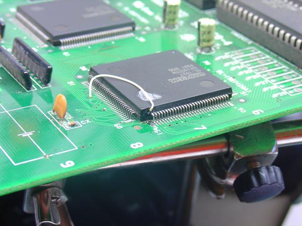
The pin is actually a Vcc pin, which is connected inside the chip to the other Vcc pins, but it's not good to rely on that because you really don't know how much current is required in each the portion of the chip. Power restored
-ud
The pin is actually a Vcc pin, which is connected inside the chip to the other Vcc pins, but it's not good to rely on that because you really don't know how much current is required in each the portion of the chip. Power restored
-ud
Righteous Super Hero / Righteous Love
-
speedlolita
- Posts: 603
- Joined: Sat Aug 15, 2009 9:13 pm
- Location: Europe
Re: Repair Log thread
Nice! Had to do something similar to that with a Japanese Saturn I had.
http://i.imgur.com/4YNnWeX.jpg
http://i.imgur.com/4YNnWeX.jpg
Re: Repair Log thread
Thanks! These are nice to read and look at!
Re: Repair Log thread
A couple years ago I had an N64 with a CPU pin eaten clean off but it still seemed to function perfectly. I checked the pinout on a working console and, sure enough, it happened to be one of numerous redundant pins to ground. Lucked out! No such luck with this one though...undamned wrote:Here's a fun one. Been going through a backlog of dead CPS2 stuff and found a 19XX which had some battery acid damage. Not nearly as bad as I'd seen before, but enough to have eaten a processor pin clean off. I had to dig into the chip body to find something to solder to:
The pin is actually a Vcc pin, which is connected inside the chip to the other Vcc pins, but it's not good to rely on that because you really don't know how much current is required in each the portion of the chip. Power restored
-ud
https://imgur.com/a/VXFbWsn

This was a Mexican N64 with an “NS9...” serial number that I bought for parts. Had a big sticker on it that said “Doesn’t Read.” Well, after my little patch, it does. Unlike the system with the missing pin, the corrosion was very hard to spot. Just looked like a darker pin on a board that actually looked pretty clean.
More/higher-res pics in the photo album linked above.
Re: Repair Log thread
Doh! Yesterday I had every single IC taken off an SHVC-CPU-01 SNES / SFC board but I forgot to take hi-res shots for future troubleshooting before I put them all back on. 

Oh well. Still figured it was worth sharing along with some under-chip PCB shots of Neo Geo AES 3-5, AES 3-6, and Turbo Duo / PC Engine Duo boards:
https://imgur.com/a/R5Et82O
Low-res sample:

Having these earlier definitely would have aided my troubleshooting. Save if you ever expect to work on these consoles!
Oh well. Still figured it was worth sharing along with some under-chip PCB shots of Neo Geo AES 3-5, AES 3-6, and Turbo Duo / PC Engine Duo boards:
https://imgur.com/a/R5Et82O
Low-res sample:
Having these earlier definitely would have aided my troubleshooting. Save if you ever expect to work on these consoles!
-
NoAffinity

- Posts: 1027
- Joined: Mon May 07, 2018 5:27 pm
- Location: Escondido, CA, USA
Re: Repair Log thread
Have repaired quite a few CPS1 A boards of all flavors - long 10mhz, short 10 mhz and DASH 12 mhz - by replacing the CPS-A-01 custom IC. CPS-A-01's can be harvested off of CPS2 A boards. While I don't condone destroying a working CPS2 A board for this purpose, if you've got one that has issues you aren't able to track down and fix, or someone is selling a partially working CPS2 A board for the right price, the CPS-A-01's are usually good donors from CPS2 A boards. They don't get utilized on CPS2 A boards, to the extent they do on CPS1 A boards, so they are likely to have a longer lifespan (and/or because they were later production, there's a likelihood they will just naturally have a longer lifespan).
At any rate, if you've isolated video anomalies to the CPS1 A board, and have any of the following issues, it is a good probability that the CPS-A-01 is failing.
-Scrolling issues
-vertical columns of jumbled or missing graphics
-Sprite mis-coloration
-Any variety of video issues that progressively worsen as the game is running
-Any variety of video issues that have progressively gotten worse over time, up to and including the game playing blind
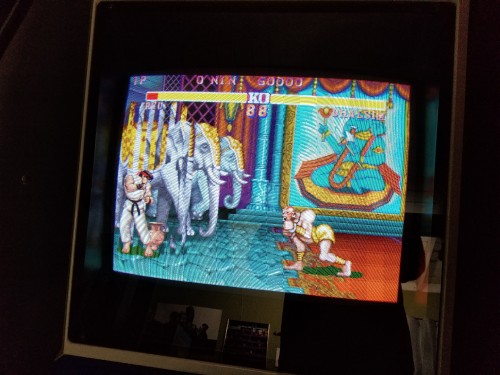
Here's an example, from a long 10mhz board I just repaired, which came off a 3 Wonders set (testing it with Street Fighter 2 World Warrior, to confirm the issue was at the A board).
 The basic process for replacement requires an above average level of soldering skill, including a hot air station. My best time, including removal and replacement, is about 2 hours.
Desoldering faulty CPS-A-01 and donor CPS-A-01
1) Lightly apply some flux to the 160 pins. A solder pen is very useful here. Use a solder braid and solder iron to remove as much of the existing solder as possible.
2) Once you have worked all four sides of the QFP IC with the solder braid, apply some more flux to the pins.
3) Also take note of, or take a picture of the positioning of the CPS1 A board’s IC, so you know how to place the replacement.
4) Use a hot air station, set to 370C, to remove the IC.
5) Take your time. It’s better to slowly work the chip off, to avoid bending pins and lifting pads. These chips are also amazingly resilient to heat. I’ve had to work them over for upwards of 20-30 minutes at times (especially on the long A boards…that solder is like cement), and I have never had one go bad during the removal process.
Soldering the donor CPS-A-01 to the CPS1 A board
1) Go over the pads on the CPS1 A board with the solder braid, to remove as much remaining solder as possible. You want the pads to all be uniformly cleaned of solder when placing and positioning the donor CPS-A-01. I also (or alternatively) use a desoldering gun like a vacuum over the pads, but you have to be careful to effectively have the nozzle float on the pads. Any kind of downward pressure, plus the heat from the nozzle, could result in pads lifting and/or being damaged.
2) Place and position the CPS-A-01. If you took your time as recommended in the removal process, then with a little bit of effort, the legs will all line up nicely with the pads. Also, if you were diligent about cleaning all solder off the pads, it makes tweaking the positioning much much easier.
3) Once you have the pins and pads all perfectly aligned, check and recheck it. It’s a lot easier to take the time positioning and making it perfect than it is to have to remove your tack-downs or even remove solder from whole rows of pins, because one of the sides wasn’t aligned well.
4) Now, once you have the IC perfectly placed and have rechecked it, tack down the corners to fix the IC in place. You don’t have to be neat about this, but you also don't want to overdo it with the amount of solder. Get a small blob of solder across a few pins at each corner, so it doesn’t move when moving to the next step.
5) Recheck the positioning against once the tack-downs are in place. If the IC got skewed while tacking it down, remove the tack downs with solder braid. You may need to apply hot air again, and restart at step 1.
6) Once tacked down, apply some more flux to all pins. You are now going to drag solder. Take your time, don’t apply to much pressure (which will bend pins). Start with dragging your tack-downs. When that solder runs out, add a small amount more to your tip and continue drag soldering.
7) Once all 160 pins are effectively soldered, check for shorts. If you can’t get rid of them by apply heat and or some more flux, the use the solder braid, and re-apply solder (and flux if needed, to make the job easier).
8 ) Then, use some ESD tweezers to check all pins for any that weren’t effectively soldered. I stick the pointy end between each pin and its neighbor, and give a very gently wiggle. Do not use too much force or you will be wasting a bunch of time reposition pins, or worse, repairing busted pins (believe me, you don’t even want to go there). For any pins you find floating, first try to drag solder from its neighbors. If that doesn’t work, apply a little bit more solder to your iron tip, and apply to the floating pin.
9) Once you are confident all pins are soldered and there are no shorts, do a quick cleaning of any residual flux. This is a good instructable on how to clean flux residue: https://www.instructables.com/id/Cleaning-up-your-PCB/
10) Now, with the IC confidently soldered in place and PCB cleaned, it's time for the smoke test. With any luck, you have been diligent at every step of the process, and the board comes up repaired. If you have different video issues or no video (including the game NOT playing blind), you probably have shorts and/or floating pins. Go back to steps 6 and 7. If you actually did get smoke, well, you probably had a short at a power pin, and have damaged the donor IC, and possibly other components. In that case, you're on your own. With that cautionary note, I will also add that I have foolishly soldered CPS-A-01's in probably every incorrect orientation, and have always corrected it to get a working board. While I obviously don't recommend orienting the chip incorrectly, just for the shear amount of time it takes to correct it, if you do get smoke it is more likely from a short.
Hopefully this is helpful.
At any rate, if you've isolated video anomalies to the CPS1 A board, and have any of the following issues, it is a good probability that the CPS-A-01 is failing.
-Scrolling issues
-vertical columns of jumbled or missing graphics
-Sprite mis-coloration
-Any variety of video issues that progressively worsen as the game is running
-Any variety of video issues that have progressively gotten worse over time, up to and including the game playing blind
Here's an example, from a long 10mhz board I just repaired, which came off a 3 Wonders set (testing it with Street Fighter 2 World Warrior, to confirm the issue was at the A board).
Spoiler
Desoldering faulty CPS-A-01 and donor CPS-A-01
1) Lightly apply some flux to the 160 pins. A solder pen is very useful here. Use a solder braid and solder iron to remove as much of the existing solder as possible.
2) Once you have worked all four sides of the QFP IC with the solder braid, apply some more flux to the pins.
3) Also take note of, or take a picture of the positioning of the CPS1 A board’s IC, so you know how to place the replacement.
4) Use a hot air station, set to 370C, to remove the IC.
5) Take your time. It’s better to slowly work the chip off, to avoid bending pins and lifting pads. These chips are also amazingly resilient to heat. I’ve had to work them over for upwards of 20-30 minutes at times (especially on the long A boards…that solder is like cement), and I have never had one go bad during the removal process.
Soldering the donor CPS-A-01 to the CPS1 A board
1) Go over the pads on the CPS1 A board with the solder braid, to remove as much remaining solder as possible. You want the pads to all be uniformly cleaned of solder when placing and positioning the donor CPS-A-01. I also (or alternatively) use a desoldering gun like a vacuum over the pads, but you have to be careful to effectively have the nozzle float on the pads. Any kind of downward pressure, plus the heat from the nozzle, could result in pads lifting and/or being damaged.
2) Place and position the CPS-A-01. If you took your time as recommended in the removal process, then with a little bit of effort, the legs will all line up nicely with the pads. Also, if you were diligent about cleaning all solder off the pads, it makes tweaking the positioning much much easier.
3) Once you have the pins and pads all perfectly aligned, check and recheck it. It’s a lot easier to take the time positioning and making it perfect than it is to have to remove your tack-downs or even remove solder from whole rows of pins, because one of the sides wasn’t aligned well.
4) Now, once you have the IC perfectly placed and have rechecked it, tack down the corners to fix the IC in place. You don’t have to be neat about this, but you also don't want to overdo it with the amount of solder. Get a small blob of solder across a few pins at each corner, so it doesn’t move when moving to the next step.
5) Recheck the positioning against once the tack-downs are in place. If the IC got skewed while tacking it down, remove the tack downs with solder braid. You may need to apply hot air again, and restart at step 1.
6) Once tacked down, apply some more flux to all pins. You are now going to drag solder. Take your time, don’t apply to much pressure (which will bend pins). Start with dragging your tack-downs. When that solder runs out, add a small amount more to your tip and continue drag soldering.
7) Once all 160 pins are effectively soldered, check for shorts. If you can’t get rid of them by apply heat and or some more flux, the use the solder braid, and re-apply solder (and flux if needed, to make the job easier).
8 ) Then, use some ESD tweezers to check all pins for any that weren’t effectively soldered. I stick the pointy end between each pin and its neighbor, and give a very gently wiggle. Do not use too much force or you will be wasting a bunch of time reposition pins, or worse, repairing busted pins (believe me, you don’t even want to go there). For any pins you find floating, first try to drag solder from its neighbors. If that doesn’t work, apply a little bit more solder to your iron tip, and apply to the floating pin.
9) Once you are confident all pins are soldered and there are no shorts, do a quick cleaning of any residual flux. This is a good instructable on how to clean flux residue: https://www.instructables.com/id/Cleaning-up-your-PCB/
10) Now, with the IC confidently soldered in place and PCB cleaned, it's time for the smoke test. With any luck, you have been diligent at every step of the process, and the board comes up repaired. If you have different video issues or no video (including the game NOT playing blind), you probably have shorts and/or floating pins. Go back to steps 6 and 7. If you actually did get smoke, well, you probably had a short at a power pin, and have damaged the donor IC, and possibly other components. In that case, you're on your own. With that cautionary note, I will also add that I have foolishly soldered CPS-A-01's in probably every incorrect orientation, and have always corrected it to get a working board. While I obviously don't recommend orienting the chip incorrectly, just for the shear amount of time it takes to correct it, if you do get smoke it is more likely from a short.
Hopefully this is helpful.

Re: Repair Log thread
@NoAffinity, thank you for the detailed write-up, much appreciated!
http://world-of-arcades.net
The future of ST-V rests upon our work and your work
The future of ST-V rests upon our work and your work
-
thomashenry
- Posts: 3
- Joined: Sat Jan 25, 2020 3:15 pm
Re: Repair Log thread
Any UK based folks here who repair CRTs?

Re: Repair Log thread
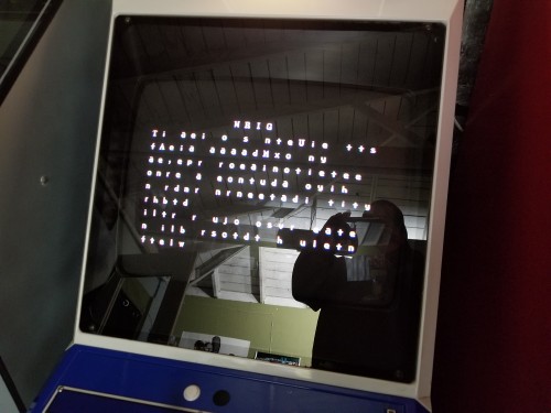
System: SNK Neo Geo MVS MV1C
Symptom: Pink "garbage" on screen at power up.
Cause: Completely dead or disabled BIOS.
Resolution: Replace BIOS with stock IC or AM27C1024 (or equivalent) programmed with working BIOS code.
I have tested disabling the BIOS on several MV1C units and always get something resembling the image below when I do. Hope this may help someone in the future.
Re: Repair Log thread
Anyone know what could cause an MVS board to have more slowdowns than another, same model board, MV1FZ ?
It's very noticiable when doing supers in LB2 with Kojiro, with the d,d+A/B I really have to compensate each input, and with qcb,f+AB each hit really slows down.
This particular board also happens to have problems with GBSC, has jumpy sync.
I tried replacing the crystal in case it drifted but same results. I tried to scope NEO-D0 clocks but I couldn't see anything different than other boards (it's a crappy scope tho).
I'm thinking LSPC2 as sync also comes from it, but it's kind of a pain to replace, so if someone ever had issue like this...
Re: Repair Log thread
Trying to figure out what transformer which is in the Sharp Famicom TV.
https://www.youtube.com/watch?v=BJdZ7fH02CU
https://www.youtube.com/watch?v=BJdZ7fH02CU

Re: Repair Log thread
Anyone U.K. based who could check out a problem with my Ultra HDMI N64?
Basically I got it ready modded from a seller on eBay - it ran fine for a year and then I started having this issue where the picture will randomly cut out and I'll be left with a black screen, though the sound will still be playing and the signal still seems to be going through to the TV. The issue can last from a few seconds to a few minutes.
I've tried a bunch of different HDMI cables and more than one TV and so I'm pretty certain it's an issue with the console - I'm told it the problem could be a "cold solder joint" which is apparently a simple fix, though I'm not technically minded at all and so I fear any attempt to fix on my part would brick the whole thing.
On the other hand the issue is becoming more persistent and I feel the console is close to becoming a £400 piece of plastic, and so willing to take the risk and try to get it mended at this point.
Obviously willing to pay any reasonable fee for services rendered
Re: Repair Log thread
Just wanted to say, that NeoGeo hardware is terrible quality and a pain in the butt to repair.
Very susceptible to corrosion (now I've used plastic spray on NeoGeos, hopefully preventing it)
Sync is terribly noisy and unclean (using LM1881 for cleaning it on all NeoGeos)
Audio grounding is also pretty messed up (unity gain opamp into a pair of 1:1 audio transformers for cleaning stereo-modded output)
And the PCBs themselves are just poor quality. Lifting a pin without ripping out the pad is amazingly tricky.
On the bright side, MVS boards are pretty cheap and repairing them is good soldering practice.
Your effort to remain what you are is what limits you.